Key points and case sharing of wireless network deployment and planning
[ad_1]
1. First, clarify a few important concepts
WLAN network architecture
The WLAN network architecture is divided into two parts: the wired side and the wireless side. The wired side refers to the AP’s uplink to the Internet network using the Ethernet protocol. The wireless side means that the network between the STA and the AP uses the 802.11 protocol. The WLAN network architecture accessed by the wireless side is a centralized architecture.
Centralized network architecture
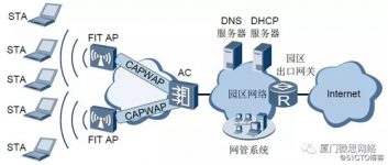
The centralized architecture is also known as the thin access point (FIT AP) architecture. Under this architecture, multiple APs are centrally managed and controlled through AC, as shown in the figure below.

Under the centralized architecture, all wireless access functions are jointly completed by AP and AC:
AC centrally handles all security, control, and management functions, such as mobility management, identity verification, VLAN division, radio frequency resource management, and data packet forwarding.
FIT AP completes wireless radio access functions, such as wireless signal transmission and detection response, data encryption and decryption, and data transmission confirmation.
The CAPWAP protocol is used for communication between AP and AC, and AP and AC can span a Layer 2 network or a Layer 3 network. The centralized architecture facilitates centralized management and maintenance by administrators.
Data forwarding method
The data in the WLAN network includes control messages and data messages. Control messages are forwarded through the CAPWAP control tunnel, and user data messages are divided into tunnel forwarding (also known as “centralized forwarding”) and direct forwarding (also known as “local forwarding” according to whether they are forwarded through CAPWAP data tunnels. )Way.
Tunnel forwarding method
The tunnel forwarding method means that after the user’s data message reaches the AP, it needs to be encapsulated in the CAPWAP data tunnel and sent to the AC, and then forwarded to the upper network by the AC, as shown in the following figure:

Direct forwarding
The direct forwarding method means that after the user’s data message arrives at the AP, it is directly forwarded to the upper network without CAPWAP tunnel encapsulation, as shown in the following figure:

Advantages and disadvantages of tunnel forwarding and direct forwarding
The advantages and disadvantages of tunnel forwarding and direct forwarding are shown in the following table:

Centralized authentication in direct forwarding mode
If the direct forwarding method is adopted, the service data is not forwarded through the AC.When a wireless user accesses the network, the user
When access authentication (for example, 802.1X authentication, etc.) and the access control point is deployed on the AC, the user’s authentication message is not available
The method is centrally managed through AC, which causes inconvenience to the administrator’s unified control of users.Direct forwarder
The centralized authentication function is enabled in the mode, and the user’s authentication message can be forwarded through the CAPWAP tunnel to the AC.
Communication data packets do not need to be forwarded by AC, as shown in the following figure:

Second, it is necessary to understand several classic application scenarios of wireless networks
Typical application of WLAN in large and medium campus networks
The large and medium-sized campus network is positioned as the headquarters of large and medium-sized enterprises, large-scale branches, universities, airports and other places. A large number of APs are deployed in a large campus WLAN.
From the perspective of network operation and maintenance and security, large and medium-sized campus networks mainly adopt a centralized (AC+FIT AP) architecture to deploy WLANs. According to the deployment method of AC, it can be divided into centralized AC solution and distributed AC solution.
Centralized AC solution
The centralized AC solution refers to the centralized deployment of AC equipment (usually independent AC equipment) in the entire network to control and manage the AP equipment of the entire network. The AC deployment can be directly connected (directly deployed between the AP and the aggregation/core switch) or by-side mode (byside the aggregation/core switch).
The centralized AC networking solution for large and medium campus networks is shown in the figure: (bypass deployment)

Typical networking application of WLAN in small campus network
Small-scale campus networks are positioned as small and medium-sized enterprises including independent small-scale campus networks, as well as scenarios where WLANs are deployed only in branch offices. The deployment scale of WLAN in a small campus network is smaller than that of a large campus but higher than that of SOHO. Compared with large-scale WLAN networks, small-scale campus network WLANs may give less consideration to network reliability, and may not require specialized network management equipment and authentication servers due to cost factors. Due to the small scale of the small campus network, a centralized AC solution is generally adopted. The deployment method of independent AC equipment or integrated AC equipment can be adopted, as shown in the figure (take independent AC equipment as an example).

Typical application of WLAN in enterprise branches
Enterprise branch WLAN networking application is a scenario where WLAN networks are deployed in both the headquarters and branches, and the headquarters needs to manage the WLAN networks of the branches.
Enterprise branches are divided into large and small based on the AC deployment mode, and there is no strict correspondence with the network scale of the branch, as shown in the following figure:

Typical applications of distributed WLAN networking
In multi-room scenarios such as hotel rooms, campus dormitories, hospital wards, etc., due to the barriers of indoor buildings such as walls, the wireless signal attenuation is more serious. Common indoor APs and indoor distributed APs cannot fully meet the requirements. Cost, high-performance wireless coverage requirements. In such scenarios, the agile distributed WLAN networking architecture can be used to deploy the network to meet such requirements.
Distributed WLAN networking includes AC+central AP+RRU, RRU sends and receives wireless messages, and transparently transmits them to the central AP for processing at the second layer. The central AP is connected to the RRU through a network cable. Compared to a common AP connected to an antenna through a feeder, the network cable can provide a longer deployment distance and facilitate the deployment of the RRU at a location farther away from the central AP.
As shown in the figure below, the central AP connects to the RRU and provides PoE power supply for the RRU. PoE switches can also be connected under the central AP, and the PoE switches can be connected to RRUs to expand the number of RRUs managed under the central AP. The RRU and the central AP that it accesses need to be a Layer 2 reachable networking and must be a tree-type networking.

Example: A campus dormitory building intends to deploy WLAN network coverage, but due to the large number of dormitory rooms in the dormitory building, obstacles such as walls between the rooms can easily seriously attenuate the wireless signal and affect the WLAN signal quality.
As shown in the figure below, the AC connects to the central AP, and the central AP connects to the RRU and provides PoE power supply for it. An RRU is deployed in each dormitory. All RRUs and central APs are centrally managed by the AC to provide high Quality WLAN network coverage.

The configuration is similar to several other application scenarios, please refer to the example configuration below in this article, and the network structure can be adjusted slightly.
3. With the above foundation, combine with a practical case

Step 1 Configure the network interworking configuration switch
Add interfaces GE0/0/1 to GE0/0/5 to VLAN 100 (AP management VLAN, used for communication between AC and AP).
The configurations on GE0/0/1 to GE0/0/5 are completely the same. Take the configuration of GE0/0/1 as an example.
system-viewsysname MaLa-Switchvlan batch 100interface gigabitethernet 0/0/1port link-type trunkport trunk pvid vlan 100port trunk allow-pass vlan 100port-isolate enablequit
Create VLANIF100~VLANIF103, VLANIF200 and VLANIF201 on the switch and configure the IP address. Among them, VLANIF100 is the gateway of AP, VLANIF101 is the gateway of office users, VLANIF102 is the gateway of development department employees, and VLANIF103 is the gateway of guest users; then configure the switch interface GE0/0/6 to join VLAN101~VLAN103 (business vlan) and VLAN200, use To carry business traffic and communicate with the switch, the interface GE0/0/24 is added to VLAN201, and the switch communicates with the router.
port link-type trunk port trunk allow-pass vlan 101 to 103 200 quitinterface gigabitethernet 0/0/24 port link-type trunk port trunk allow-pass vlan 201 quit
AC configuration: Add GE0/0/6, which connects the AC to the switch, to VLAN101~VLAN103 and VLAN200.
system-view[AC6605] sysname AC[AC] vlan batch 101 to 103 200[AC] interface vlanif 200[AC-Vlanif200] ip address 10.10.200.1 24[AC-Vlanif200] quit[AC] interface gigabitethernet 0/0/1[AC-GigabitEthernet0/0/1] port link-type trunk[AC-GigabitEthernet0/0/1] port trunk allow-pass vlan 101 to 103 200[AC-GigabitEthernet0/0/1] quit
Egress router configuration: configure the route to the Switch.
ip route-static 172.16.100.0 24 10.10.201.2 ip route-static 172.16.101.0 24 10.10.201.2 ip route-static 172.16.102.0 24 10.10.201.2 ip route-static 172.16.103.0 24 10.10.201.2
Configure the default route of the Switch, the next hop is VLANIF201 of Router.
[Switch_B] ip route-static 0.0.0.0 0.0.0.0 10.10.201.1
Configure the route from AC to AP, and the next hop is VLANIF200 of the Switch.
[AC] ip route-static 172.16.100.0 24 10.10.200.2
Step 2 Configure the DHCP service to assign IP addresses to APs and terminals
Configure the Switch as a DHCP server to assign IP addresses to APs and terminals. When the AP and AC are in a Layer 3 network, you need to configure Option 43 to advertise the AC’s IP address to the AP.
dhcp enableip pool apnetwork 172.16.100.0 mask 24gateway-list 172.16.100.254option 43 sub-option 3 ascii 10.10.200.1quitip pool BanGongnetwork 172.16.101.0 mask 24gateway-list 172.16.101.254Dns-list 114.114.114.114quitip pool KaiFanetwork 172.16.102.0 mask 24gateway-list 172.16.102.254Dns-list 114.114.114.114quitip pool Guestnetwork 172.16.103.0 mask 24gateway-list 172.16.103.254Dns-list 114.114.114.114quit
Step 3 Configure VLAN pool to carry wireless service VLAN
Create 3 VLAN pools, BanGong, KaiFa, and Guest, and add VLAN101 and VLAN102,103 to the corresponding vlan pools respectively
Note: The concept in the VLAN pool in this example is: VLANs are used to isolate terminals on the AC. If the number of terminals is large, for example, more than 255, a VLAN pool can contain 2 or more VLANs, each VLAN Corresponding to a network segment, by isolating the user’s broadcast domain, the impact on the performance of the wireless network is reduced. The algorithm for VLAN assignment is configured as “hash”. The allocation algorithm is “hash” by default. If you have not modified its default configuration before, you do not need to execute the assignment hash command.
In this example, the VLAN pool only takes the addition of VLAN101 and VLAN102 as an example. You can actually configure multiple VLANs to join the VLANpool. The configuration method is the same as that of VLAN101 and VLAN102. You also need to create a corresponding VLANIF interface and configure an IP address on Switch_B. Configure the IP address pool.
vlan pool mala-BanGongvlan 101assignment hashquitvlan pool mala-KaiFavlan 102assignment hashquitvlan pool mala-Guestvlan 103assignment hashquit
Step 4 Configure AP to go online
Create 3 AP groups “XX-BanGong” and “XX-KaiFa” and “XX-Guest”.
[AC] wlan[AC-wlan-view] ap-group name XX-BanGong[AC-wlan-ap-group-BanGong] quit[AC-wlan-view] ap-group name XX-KaiFa[AC-wlan-ap-group-KaiFa] quit[AC-wlan-view] ap-group name XX-Guest[AC-wlan-ap-group-Guest] quit
Create a domain management template, configure the AC country code under the domain management template, and reference the domain management template under the AP group.
[AC-wlan-view] regulatory-domain-profile name domain1[AC-wlan-regulatory-domain-prof-domain1] country-code cn[AC-wlan-regulatory-domain-prof-domain1] quit[AC-wlan-view] ap-group name XX-BanGong[AC-wlan-ap-group-XX-bangong] regulatory-domain-profile domain1Warning: Modifying the country code will clear channel, power and antenna gain configurations of the radio and reset the AP. Continue?[Y/N]:y[AC-wlan-ap-group-XX-banggong] quit[AC-wlan-view] ap-group name MaLa-KaiFa[AC-wlan-ap-group-XX-kaifa] regulatory-domain-profile domain1Warning: Modifying the country code will clear channel, power and antenna gain configurations of the radio and reset the AP. Continue?[Y/N]:y[AC-wlan-ap-group-Mala-kaifa] quit
[AC-wlan-view] ap-group name XX-Guest[AC-wlan-ap-group-XX-Guest] regulatory-domain-profile domain1Warning: Modifying the country code will clear channel, power and antenna gain configurations of the radio and reset the AP. Continue?[Y/N]:y[AC-wlan-ap-group-XX-Guest] quit
Configure the source interface of the AC.
[AC] capwap source interface vlanif 200 **This command is very important!!**
Import the AP offline on the AC. All APs deployed in the reception lobby are added to the AP group “XX-guest”, APs deployed in the office area are added to the AP group “XX-BanGong”, and those deployed in the office area on the 2nd floor are added to “XX-kaifa” and are based on The deployment location of the AP is the AP configuration name, so that you can know the deployment location of the AP from the name. For example, an AP with a MAC address of 60de-4474-9640 is deployed in Room 1 on the second floor of an office area, and the AP is named “Bangong-AP1”.
illustrate
The ap auth-mode command is MAC authentication by default. If you have not modified its default configuration before, you do not need to execute ap authmode
mac-auth.
The AP used in the example is AP6010DN-AGN, which has two radios: radio 0 and radio 1. AP6010DN-AGN radio frequency 0 is
2.4GHz radio frequency, radio frequency 1 is 5GHz radio frequency.
[AC] wlan[AC-wlan-view] ap auth-mode mac-auth[AC-wlan-view] ap-id 1 ap-mac 60de-4476-e360[AC-wlan-ap-0] ap-name ap1[AC-wlan-ap-0] ap-group XX-bangongWarning: This operation may cause AP reset. If the country code changes, it will clear channel,power and antenna gain configurations of the radio, Whether to continue? [Y/N]:y[AC-wlan-ap-0] quit[AC-wlan-view] ap-id 2 ap-mac 60de-4476-e380[AC-wlan-ap-1] ap-name ap2[AC-wlan-ap-1] ap-group XX-bangongWarning: This operation may cause AP reset. If the country code changes, it will clear channel,power and antenna gain configurations of the radio, Whether to continue? [Y/N]:y[AC-wlan-ap-1] quit[AC-wlan-view] ap-id 3 ap-mac 60de-4474-9640[AC-wlan-ap-2] ap-name ap3[AC-wlan-ap-2] ap-group XX-kaifaWarning: This operation may cause AP reset. If the country code changes, it will clear channel,power and antenna gain configurations of the radio, Whether to continue? [Y/N]:y[AC-wlan-ap-2] quit[AC-wlan-view] ap-id 4 ap-mac 60de-4474-9660[AC-wlan-ap-3] ap-name mala-kaifa[AC-wlan-ap-3] ap-group employeeWarning: This operation may cause AP reset. If the country code changes, it will clear channel,power and antenna gain configurations of the radio, Whether to continue? [Y/N]:y[AC-wlan-ap-3] quit[AC-wlan-view] ap-id 5 ap-mac 60de-4474-9660[AC-wlan-ap-3] ap-name ap5[AC-wlan-ap-3] ap-group XX-guestWarning: This operation may cause AP reset. If the country code changes, it will clear channel,power and antenna gain configurations of the radio, Whether to continue? [Y/N]:y[AC-wlan-ap-3] quit
After the AP is powered on, when the “State” field of the AP is displayed as “nor” by executing the display ap all command, it means
The AP goes online normally.
[AC-wlan-view] display ap allTotal AP information:nor: normal [4]————————————————– ——————————————–ID MAC Name Group IP Type State STA Uptime———————————————– ———————————————–0 60de- 4474-9640 office2-1 employee 10.23.100.253 AP6010DN-AGN nor 0 2H:30M:1S1 60de-4474-9660 office2-2 employee 10.23.100.251 AP6010DN-AGN nor 0 2H:35M:2S2 60de-4476-e360 lobby-1 guest 10.23.100.254 AP6010DN-AGN nor 0 2H:29M:29S3 60de-4476-e380 lobby-2 guest 10.23.100.252 AP6010DN-AGN nor 0 2H:34M:11S————– ————————————————– ——————————Total: 4
Step 5 Configure WLAN service parameters
Create security templates named “XX-bangong” and “XX-kaifa”, mala-guest, and configure security policies.
Note: In the example, configure the security policy of WPA2+PSK+AES as an example. The passwords are “XXXX” and “XXXX” respectively. In the actual configuration, please configure the security policy that meets the actual requirements according to the actual situation.
[AC-wlan-view] security-profile name mala-bangong[AC-wlan-sec-prof-guest] security wpa2 psk pass-phrase XXX aes[AC-wlan-sec-prof-guest] quit[AC-wlan-view] security-profile name mala-kaifa[AC-wlan-sec-prof-employee] security wpa2 psk pass-phrase XXX aes[AC-wlan-sec-prof-employee] quit[AC-wlan-view] security-profile name mala-guest[AC-wlan-sec-prof-employee] security wpa2 psk pass-phrase XXX aes[AC-wlan-sec-prof-employee] quit
Create SSID templates named “XX-bangong” and “XX-kaifa” XX-guest, and configure the SSID names respectively.
[AC-wlan-view] ssid-profile name XX-bangong[AC-wlan-ssid-prof-guest] ssid XX-BanGongWarning: This action may cause service interruption. Continue?[Y/N]y[AC-wlan-ssid-prof-guest] quit[AC-wlan-view] ssid-profile nameXX-kaifa[AC-wlan-ssid-prof-employee] ssid XX-kaifaWarning: This action may cause service interruption. Continue?[Y/N]y[AC-wlan-ssid-prof-employee] quit[AC-wlan-view] ssid-profile name XX-guest[AC-wlan-ssid-prof-employee] ssid XX-guestWarning: This action may cause service interruption. Continue?[Y/N]y[AC-wlan-ssid-prof-employee] quit
Create VAP templates named “XX-bangong” and “XX-kaifa”, XX-guest, configure the service data forwarding mode, service VLAN, and reference the security template and SSID template.
[AC-wlan-view] vap-profile name XX-bangong[AC-wlan-vap-prof-guest] forward-mode tunnelWarning: This action may cause service interruption. Continue?[Y/N]y[AC-wlan-vap-prof-guest] service-vlan vlan-pool XX-bangong[AC-wlan-vap-prof-guest] security-profile XX-bangong[AC-wlan-vap-prof-guest] ssid-profile XX-bangong[AC-wlan-vap-prof-guest] quit
The rest is similar and will not be repeated.
Configure the AP group to reference the VAP template. If the AP supports dual-frequency, both radio 0 and radio 1 on the AP use the configuration of the VAP template.
[AC-wlan-view] ap-group name XX-bangong[AC-wlan-ap-group-guest] vap-profile XX-bangong wlan 1 radio 0[AC-wlan-ap-group-guest] vap-profileXX-bangong 1 radio 1[AC-wlan-ap-group-guest] quit
The rest is similar and will not be repeated.
Step 6 Verify the configuration result
The WLAN service configuration will be automatically issued to the AP. After the configuration is completed, execute the command display vap ssid guest and
display vap ssid employee to view the following information, when the “Status” item is displayed as “ON”, it means that the AP is
The VAP on the corresponding radio has been created successfully.
[AC-wlan-view] display vap ssid guestWID: WLAN ID——————————————- ————————————-AP ID AP name RfID WID BSSID Status Auth type STA SSID- ————————————————– —————————– 0 lobby-1 0 1 60DE-4476-E360 ON WPA2-PSK 1 guest0 lobby-1 1 1 60DE-4476-E370 ON WPA2-PSK 0 guest1 lobby-2 0 1 60DE-4476-E380 ON WPA2-PSK 1 guest1 lobby-2 1 1 60DE-4476-E390 ON WPA2-PSK 0 guest—— ————————————————– ———————–Total: 4[AC-wlan-view] display vap ssid employeeWID: WLAN ID——————————————- ————————————-AP ID AP name RfID WID BSSID Status Auth type STA SSID- ————————————————– —————————–2 office2-1 0 1 60DE-4474-9640 ON WPA2-PSK 0 employee2 office2-1 1 1 60DE-4474-9650 ON WPA2-PSK 1 employee3 office2-2 0 1 60DE-4474-9660 ON WPA2-PSK 0 employee3 office2-2 1 1 60DE-4474-9670 ON WPA2-PSK 1 employee—— ————————————————– ———————–Total: 4 End users searched for “XX-BanGong” and “XX-kaifa”, “XX-guest” For wireless network, enter the passwords “XXXX” and “XXXX” and associate normally, execute the display station ssid guest and display station ssid XXXX (ssid name) commands on the AC, you can see that the users have been connected to the wireless network “guest” “And “employee”.[AC-wlan-view] display station ssid guestRf/WLAN: Radio ID/WLAN IDRx/Tx: link receive rate/link transmit rate(Mbps)————————- ————————————————– —STA MAC AP ID Ap name Rf/WLAN Band Type Rx/Tx RSSI VLAN IP address—————————– ————————————————-581f -28fc-7ead 0 lobby-1 0/1 2.4G 11n 2/4 -53 101 10.23.101.254————————— ————————————————– -Total: 1 2.4G: 1 5G: 0[AC-wlan-view] display station ssid employeeRf/WLAN: Radio ID/WLAN IDRx/Tx: link receive rate/link transmit rate(Mbps)————————- ————————————————– —STA MAC AP ID Ap name Rf/WLAN Band Type Rx/Tx RSSI VLAN IP address—————————– ————————————————-e019 -1dc7-1e08 2 office2-1 1/1 5G 11n 26/51 -61 102 10.23.103.254—————————- ————————————————– Total: 1 2.4G: 0 5G: 1
Four, summary
Of course, there are a lot of conceptual knowledge involved in wireless, such as: wireless frame structure, CAPWAP principle, client active/passive scanning, AP online registration process and other technical principles, Huawei’s official document has a very detailed introduction, in This will not be repeated here.
[ad_2]


