Application cases of Fengwang Technology’s wireless sensor products in the chemical industry
[ad_1]
1 Overview
The equipment in the petroleum and chemical industry is mainly composed of various refining or chemical units. The refining system is mainly composed of atmospheric and vacuum units, catalytic cracking units, hydrogenation or reforming units, and the chemical system is mainly composed of olefin units (such as ethylene units, polypropylene units, etc. ,) compounding units (such as isopropanol units, heavy aromatics units), etc. The main equipment of these process units are basically large rotating machinery, and the key equipment in the petrochemical industry. Smoke generators, fans, steam turbine units, etc. directly affect the safety production and economic benefits of the factory. The above three units all have the characteristics of large unit capacity, large rotor volume and high speed, and all large units need to ensure long-term stable operation. High requirements are placed on equipment management and monitoring. In recent years, large-scale rotating unit failure accidents in the domestic petrochemical industry have occurred frequently. Implementing a high-reliability online monitoring and fault diagnosis system for large-scale rotating units that meets the needs of the petrochemical industry is an important part of realizing production safety and stable and long-term operation of equipment in the petrochemical industry. It is also the need for modern equipment management in the petrochemical industry.
The wireless sensing system of Wuhan Fengwang Technology Co., Ltd. adopts 2.4G direct-sequence spread spectrum, and uses temperature, pressure, vibration, and flow sensors to collect data in real time through 2.4G wireless modules or ZigBee, and transmit the data back to the computer center ERP Software management system; or connect to the Internet LAN through GPRS, or send information such as equipment status to relevant personnel’s mobile phones by SMS, which greatly improves the safety production efficiency of enterprises.
2. System composition
---Pressure data acquisition equipment
---Vibration data acquisition equipment
---Temperature data acquisition equipment
---Flow data collection equipment
---Wireless relay
---Wireless Center
---Computer management software
3. Equipment introduction

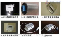
a. Pressure data acquisition equipment – for (water, gas, hydraulic, oil pressure) pipelines, boilers, pressure tanks, reaction towers, large mechanical equipment, cranes, tower cranes, etc. pressure data acquisition and wireless transmission. It is usually installed independently on site, and can regularly send the detected data to the nearest relay station, and the relay station transmits it to the receiving center, or it can transmit data point-to-point (for example, it can be transmitted to a PLC programmable controller)
b. Pressure data acquisition equipment – used for surface vibration data acquisition and wireless transmission, usually installed independently on site, and periodically sends the detected data to the nearest relay station, and the relay station transmits it to the receiving center.
c. Temperature data acquisition equipment – used for object surface temperature data acquisition and wireless transmission, usually installed independently on site, regularly sending the detected data to the nearest relay station, and the relay station will transmit it to the receiving center.
d. Flow data acquisition equipment – used for liquid or gas flow data acquisition and wireless transmission, can be used with various flowmeters such as electromagnetic flowmeters, electromagnetic flowmeters, etc., to regularly send the detected data to the nearest relay station, by The relay station transmits it to the receiving center.
e. Wireless relay – used for long-distance or different detection area data wireless relay transmission (also known as relay transmission), it is the main equipment for establishing wireless network communication for equipment point inspection. Usually, its use is determined according to the physical location of the equipment to be inspected on site, its distribution quantity can reflect its network coverage, and it has path setting requirements. For example: when the physical location of the wireless receiving center of the system is determined, the center can receive the point inspection data information returned by multiple path relay stations. The relay stations of each path are composed of multiple relay stations and have their own path serial numbers. The relay station transmits information according to its serial number.
f. Wireless center – a link device from wireless to wired, because this equipment point inspection and early warning system is developed based on the Ethernet platform, so the data acquisition and transmission are connected to the computer system through any workstation on the Ethernet, and the system can usually be set to 1 ~2 central access points. Each central station can receive the inspection data information returned by the relay stations of multiple paths.
4. Computer management software
a.Operating environment
Win9X/NT/2000/XP/2003
b.Login management

c. Interface management

5. System block diagram

[ad_2]


