
 chrispeng
 RFID Charging System Design: A Modern Approach Using CAN Bus and 2.4G Wireless Technology
1. Introduction: Overcoming Limitations in Traditional RFID Charging Systems
Radio Frequency Identification (RFID) technology has become the backbone of modern automated charging systems, powering applications from public transit fare collection to parking lot management and toll road operations. These systems rely on seamless, real-time data exchange between RFID readers and central control units to process transactions efficiently and accurately.
For years, the industry standard for communication in these systems has been the RS-485 bus. While robust and widely understood, RS-485 operates on a single-master, polling-based architecture. This creates inherent limitations: it struggles with low real-time performance, relatively low communication efficiency, and poor scalability in larger deployments. When multiple RFID terminals need to report transactions simultaneously, the polling mechanism introduces latency that can lead to bottlenecks, especially during peak usage hours.
As a manufacturer of advanced RFID solutions, we recognized the need for a system architecture that eliminates these bottlenecks while maintaining the reliability essential for financial transactions. This article presents a complete design scheme for an RFID charging system that replaces the conventional RS-485 bus with a Controller Area Network (CAN) bus combined with 2.4GHz wireless communication. The result is a system that delivers superior real-time performance, enhanced reliability, and significantly reduced wiring complexity.
2. System Architecture: The CAN Bus and 2.4G Wireless Network
2.1 Why CAN Bus Replaces RS-485
The Controller Area Network (CAN) bus was originally developed for automotive applications where reliability and real-time response are critical. Unlike RS-485, the CAN bus employs a multi-master architecture. Any node on the network can initiate data transmission at any time, eliminating the need for polling and vastly improving response times. This makes it ideally suited for RFID charging systems where multiple readers may need to transmit transaction data simultaneously.
Key advantages of the CAN bus in this application include:
- Non-destructive arbitration: When two or more nodes attempt to transmit simultaneously, the node with the highest priority (lowest identifier) automatically wins arbitration, while lower-priority nodes cease transmission and retry. This ensures critical transactions are never lost.
- Exceptional error detection: Every CAN frame includes CRC checking and other error detection mechanisms, ensuring data integrity critical for financial transactions.
- Fault confinement: If a node experiences a serious error, it automatically disconnects from the bus, preventing it from disrupting other nodes.
- Long-distance communication: CAN supports distances up to 10km at 5kbps, with data rates up to 1Mbps for shorter distances.
2.2 The Role of 2.4G Wireless Networking
In many real-world environments, running cable to every RFID terminal is impractical, expensive, or aesthetically undesirable. This design incorporates the nRF24L01 2.4GHz wireless transceiver chip to create a wireless bridge between the RFID reader modules and the CAN bus backbone. The nRF24L01 supports multi-point communication capability, allowing a single CAN node to receive data from up to six different RFID terminals. This dramatically reduces both wiring requirements and installation costs while maintaining high data throughput.
The combination of CAN bus and 2.4G wireless networking creates a hybrid architecture that offers the best of both worlds: the reliability and fault tolerance of a wired fieldbus for the backbone, combined with the flexibility and low installation cost of wireless connections at the endpoint level.
3. Hardware System Design
3.1 System Topology
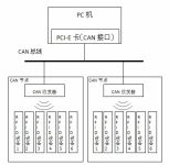
The complete system is organized into two subsystem types:
- Subsystem A (CAN Node): Contains a microcontroller (STC89LE58RD+), nRF24L01 wireless module, watchdog timer, and CAN module (SJA1000 controller + PCA82C250 transceiver). This subsystem receives data wirelessly from up to six B subsystems and transmits it to the PC via the CAN bus.
- Subsystem B (RFID Terminal): Contains a microcontroller, MF RC500 RFID reader module, nRF24L01 wireless module, LCD display, keypad, real-time clock, EEPROM, and watchdog. This subsystem handles the actual card reading and user interface functions.
3.2 Core Component Selection
Microcontroller: STC89LE58RD+
This 8-bit microcontroller offers 32KB of Flash ROM, 1280 bytes of RAM, three timers, and eight interrupt sources with four priority levels. Its 4-port I/O structure provides ample connectivity for peripheral modules while maintaining low power consumption suitable for continuous operation in charging stations.
CAN Controller and Transceiver
The Philips SJA1000 is an independent CAN controller supporting both BasicCAN and PeliCAN modes. In PeliCAN mode, it implements the CAN 2.0B protocol with extended 29-bit identifiers, providing the addressing flexibility needed for large-scale deployments. The PCA82C250 transceiver connects the SJA1000 to the physical CAN bus, providing differential transmission and reception with protection against electromagnetic interference and thermal overload. Up to 110 nodes can be connected on a single bus segment.
Wireless Module: nRF24L01
Operating in the license-free 2.4GHz ISM band, this transceiver supports data rates up to 2Mbps with 125 selectable frequency channels. Its ShockBurst™ mode allows connection with low-speed microcontrollers while maintaining efficient packet handling. The automatic acknowledgment feature ensures reliable delivery by confirming successful reception, and the device can receive on up to six different data channels simultaneously.
RFID Reader: MF RC500
The MF RC500 is a highly integrated reader IC that supports the ISO 14443A protocol for communication with MIFARE Classic cards. It features a 64-byte FIFO buffer for efficient data streaming, integrated demodulation and decoding circuitry, and a non-volatile key memory for secure authentication operations. The device operates at 13.56MHz and provides the energy carrier needed to power passive RFID tags.
4. Software System Design and Communication Protocols
4.1 Wireless Communication Protocol
Subsystem B is configured as a transmitter using 16-bit CRC checking and the automatic acknowledgment feature. Each B subsystem is assigned a unique transmission address, and the A subsystem’s receiver is configured with six reception channels, each programmed with one of the B subsystem addresses. This addressing scheme ensures that data from each RFID terminal is correctly routed.
The software flow for Subsystem A begins with initialization of the CAN controller, wireless module, and external interrupt system. Upon receiving an interrupt from the nRF24L01 indicating data arrival, the microcontroller reads the wireless data, formats it into a CAN frame, and transmits it onto the CAN bus. The PC receives the data through a PCI-E CAN interface card.
For Subsystem B, the software flow involves initializing the RFID reader, displaying status on the LCD, and entering a waiting state. When a MIFARE card is detected, the system executes the anti-collision algorithm, selects the card, performs authentication using the stored key, and conducts the read/write transaction. The resulting data is packaged and transmitted wirelessly to Subsystem A.
4.2 CAN Bus Protocol
The CAN bus is configured at 125kbps baud rate using PeliCAN mode with 29-bit identifiers. The acceptance code and mask registers are programmed to implement message filtering at the hardware level, ensuring that each node only processes messages relevant to its function. Data transmission uses query-based confirmation: the microcontroller checks the Transmit Buffer Status (TBS), Transmission Complete Status (TCS), and Transmit Status (TS) flags in the SJA1000 status register to verify successful transmission.
5. Real-World Applications and Use Cases
5.1 Public Transit Fare Collection
In bus and metro systems, the hybrid wireless-CAN architecture enables rapid processing of fare transactions as passengers board. The wireless link eliminates the need to run data cables through vehicles, while the CAN bus backbone ensures that fare data from multiple entry points reaches the central controller without collisions or delays.
5.2 Parking Lot Management
For parking facilities with multiple entry and exit lanes, the six-channel wireless receiver capability allows a single CAN node to manage up to six RFID readers, reducing infrastructure costs. The system can handle peak-hour traffic without data loss, and the CAN bus fault confinement ensures that a single faulty reader does not affect operations across the facility.
5.3 Campus and Corporate Access Control
These systems benefit from the long-distance communication capability of CAN bus, enabling centralized management of access points distributed across large campuses. The wireless connectivity simplifies retrofitting into existing buildings where running new cables would be disruptive.
6. Deployment Considerations
6.1 Installation Planning
When deploying this system, consider the following factors:
- Wireless range: The nRF24L01 typically achieves 30-50 meters in indoor environments with line-of-sight. For longer distances or through walls, consider adding repeater nodes or extending the CAN bus backbone closer to the wireless endpoints.
- Frequency planning: With 125 available channels, neighboring installations can operate on different channels to avoid interference. Channel selection should account for other 2.4GHz devices in the environment.
- Power supply: Each CAN node can supply power to its associated wireless receivers. RFID terminals require local power; consider Power over Ethernet (PoE) alternatives for cleaner installations.
- Cable termination: Proper termination resistors (120Ω) must be installed at both ends of the CAN bus to prevent signal reflections.
6.2 Selecting the Right RFID Tags
The system is designed primarily for MIFARE Classic cards operating at 13.56MHz. However, the MF RC500 reader can also interact with other ISO 14443A compliant RFID tags. For applications requiring different tag form factors or read ranges, hardware modifications may be necessary. Consider consulting with your RFID tag supplier to select the optimal tag for your specific use case, whether for payment cards, wristbands, or adhesive labels.
For applications involving RFID tags on clothes, such as laundry or uniform management, the choice of tag substrate and attachment method becomes critical. High-temperature washing and drying cycles require specially encapsulated tags that can withstand the harsh environment. The wireless data transmission architecture described here can easily accommodate such specialized tag types by adjusting the reader configuration parameters.
7. System Testing and Performance Validation
After constructing the prototype system, comprehensive testing was conducted. The RFID module successfully read and wrote to MIFARE 1 cards within the antenna effective range, with card data displayed correctly on the LCD.
To validate the real-time performance of the transmission network, temperature data from DS18B20 sensors was transmitted through the complete system chain: sensor → Subsystem B microcontroller → nRF24L01 wireless link → Subsystem A → CAN bus → PC. Temperature readings were sampled every second and transmitted continuously over a 24-hour period. The PC-side application, developed in Visual Basic 6.0, plotted the temperature curve and logged all data points.
Analysis of the temperature data revealed no anomalies, missing data points, or transmission errors. The temperature values maintained 1°C precision as expected, and the continuous logging demonstrated the system’s ability to handle sustained real-time data flow without buffer overflow or data loss.
8. Product Selection Guidance for System Integrators
When building an RFID charging system based on this architecture, careful component selection is essential for reliability and cost-effectiveness. The choice of RFID tags directly impacts system performance. For payment applications requiring high security, select tags with encryption and authentication capabilities. For simpler identification applications where cost is a primary concern, consider using standard compliant tags.
When comparing tag options for your charging system, understanding the differences between tag types is crucial. For NFC-based applications, understanding which NFC IC to choose can make a significant difference in performance and cost. For instance, the NTAG213 vs NTAG215 comparison highlights differences in memory capacity and features—NTAG215 offers 504 bytes versus NTAG213’s 180 bytes, making it more suitable for storing additional data like loyalty points or user profiles alongside payment credentials.
For applications requiring longer read ranges or specialized form factors, understanding the differences between tag technologies is important. The HDX vs FDX tags distinction becomes relevant when considering reader compatibility and performance requirements. For a detailed comparison of specific NFC chip options, consult our guide on NTAG215 versus other available solutions to determine the optimal choice for your charging system deployment.
9. Conclusion
This article has presented a complete design scheme for an RFID charging system that replaces the traditional RS-485 bus with a CAN bus architecture combined with 2.4GHz wireless networking. The system leverages the multi-master capability, non-destructive arbitration, error detection, and fault confinement of the CAN bus to achieve superior real-time performance and reliability compared to conventional designs.
The integration of nRF24L01 wireless modules eliminates the need for extensive cabling to each RFID terminal while supporting up to six terminals per CAN node. The system has been thoroughly tested with continuous data transmission over extended periods, demonstrating stable, reliable, and real-time performance suitable for financial transaction applications in public transit, parking management, and access control environments.
By adopting this hybrid wired-wireless architecture, system integrators can achieve a balance between reliability, cost-effectiveness, and deployment flexibility that meets the demands of modern automated charging and payment systems.
10. Frequently Asked Questions (FAQ)
Q1: What is the maximum distance between the RFID terminal and the CAN node in this system?
The nRF24L01 wireless module typically provides reliable communication up to 30-50 meters indoors with clear line-of-sight. For longer distances, extend the CAN bus backbone to position additional A subsystems closer to the B subsystems, or consider using higher-gain antennas.
Q2: Can this system be used with RFID tags other than MIFARE Classic?
Yes, the MF RC500 reader supports the ISO 14443A standard. Any compliant tag, including custom RFID stickers and NFC tags, can be used with appropriate reader configuration changes. For other protocols (e.g., 125kHz tags), the RFID module must be replaced with a compatible reader.
Q3: How many RFID terminals can one CAN bus support?
The PCA82C250 transceiver supports up to 110 nodes on a single bus. With each A subsystem supporting six B subsystems, this translates to up to 660 RFID terminals per CAN bus segment.
Q4: What happens if a wireless link fails during a transaction?
The nRF24L01’s automatic acknowledgment feature ensures reliable delivery. If no acknowledgment is received, the transmitting B subsystem can retry the transmission. Multiple retries with timeout mechanisms ensure data is not lost. Additionally, EEPROM storage at the B subsystem provides non-volatile transaction logging as a backup.
Q5: Is this system suitable for outdoor installations?
Yes, with appropriate enclosures rated for outdoor use (IP65 or higher). The PCA82C250 transceiver includes protection against electromagnetic interference, and the CAN bus is inherently robust for industrial environments. Wireless performance may be affected by rain or dense foliage, so site surveys are recommended.
Q6: What power consumption can be expected from each subsystem?
The STC89LE58RD+ microcontroller consumes under 20mA at 3.3V operation. The nRF24L01 transmits at approximately 11mA peak. The MF RC500 draws up to 80mA during operation. Total B subsystem power consumption is typically under 150mA, making it suitable for battery-backed or low-power installations.
Q7: How does the system handle card authentication and security?
The MF RC500 supports the MIFARE authentication protocol, matching the card’s password against keys stored in its non-volatile memory. For higher security, the system can be extended to support 3DES or AES encryption by upgrading the reader IC. All CAN bus data can also be encrypted at the application layer if required.
Q8: What software tools are needed to monitor and manage the CAN bus?
The PC requires a PCI-E CAN interface card and compatible driver software. The system described uses a Visual Basic 6.0 application for data visualization and logging. Commercial CAN bus analysis tools like PCAN-View or CANalyzer can also be used for system debugging and performance monitoring.