Application of RFID technology in the production line of casting two core making
[ad_1]
The casting two core production line is mainly composed of two core production centers consisting of Loramendi core shooters, ABB robots, conveyor roller tables, surface drying furnaces and other equipment. The main production line is for the production of automotive engine cylinder head sand core production lines. It was officially put into production in 2013 and is currently one of the most advanced casting production lines in the world. In order to meet market demand, Cast 2 often needs to produce core sand of different models at the same time. Therefore, RFID technology is used to accurately record and transmit the model of each sand core and other production information, and automatically achieve core shooting, core assembly, dipping, and coating. Sand core baking, drilling, core combining, handling, core setting and other core making process requirements.
RFID system composition and working principle
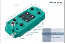
The RFID system mainly includes three parts: the controller, the read-write head and the code carrier. The controllers used in casting two core making are: C-KP2-1HB6-V15B single-channel controller, IC-KP2-2HB6-V15B dual-channel controller, IC-KP-B6-V15B four-channel controller, as shown in Figure 1. As shown in Figure 2 and Figure 3.

Figure 1 Dual-channel controller (read-write head model: IQH-FP-V1)

Figure 2 Read-write head (code carrier model: IQC21-85-T13)

Figure 3 Code carrier
The RFID control system is connected with the upper-level control equipment PLC. On the one hand, it receives the data information operation instructions sent by the PLC, converts them into read/write instructions and sends them to the read/write head. On the other hand, it will receive the data from the read/write head. The information is sent to the PLC. RFID communication protocols include Profibus-DP, Profinet I/O, Ethernet/IP, DeviceNet, Modbus/TCP? TCP/IP, Interbus, CAN Bus, Serial (RS232, RS485), etc. The code carrier of the casting two core production line is installed on the pallet conveyed by the roller conveyor. The RFID system is a part of the entire roller conveyor, which is controlled by Profibus-DP communication.
RFID control system configuration and program structure
RFID control system configuration
(1) Install GSD file
The GSD file is a device hardware description file, which contains information about all bus systems to connected devices. Open the hardware configuration tool HW Config in the SIMATIC Manager of S7. If the required configuration does not appear in the DP slave window, you need to download the GSD file.
The GSD file can be downloaded on the official website of P+F. After the GSD file is downloaded successfully, as shown in Figure 4, in the hardware structure window, click Options and select the “Install GSD File” command.

Figure 4 Install GSD file 1

Figure 5 Install GSD file 2
In the pop-up window, Browse looks for the downloaded GSD file and installs it, as shown in Figure 5.
(2) Profibus settings
After opening the STEP7 hardware settings, the system will automatically add the CPU and DP ports to the configuration column. Here manually add the power supply model used. After completing the most basic PLC hardware settings, you can set the Profibus-DP bus system communication and hardware address parameters, as shown in Figure 6.

Figure 6 Hardware connection settings
Find the identification controller that matches the hardware on the Profibus-DP master station. As shown in Figure 7, find the required identification controller IC-KP2-xHB6 A on the right side of the window. The user can define the Profibus that can identify the controller. the address of.
After adding the identification controller to the DP bus, you need to set the device input/output bytes. The setting depends on the working mode required by the user. Here, select In/Out 32 Byte.

Figure 7 Hardware connection settings
The address of the added module can be automatically assigned by PLC, or it can be changed according to its own needs. A simple RFID hardware setting configuration column is completed, and then it is downloaded to the PLC. Figure 8 shows the PLC hardware configuration of the storage line of the cast two-core roller table.

Figure 8 Casting two core storage line hardware group
RFID control program structure
(1) Call the function block “IDENTControl”
The “IDENTControl” multifunctional integrated block of the P+F controller, provided by P+F, can be freely copied and called in the SIMATIC Manager platform. The function block extracts the variables that need to be applied, and displays it briefly and clearly in the program Come out, convenient for users to use.
Users can copy the function blocks and background data blocks provided by Pepperl+Fuchs to the user program, and call the function blocks in the program. When there are multiple devices in the bus that need to call the function block, you only need to create background data blocks for different devices, and call the corresponding background data blocks through the function block. For example:
CALL FB300, DB300
CALL FB300, DB301…

Figure 9 Function blocks called by the program
(2) The meaning of the variable of the function block “IDENTControl” The meaning of the variable is shown in Figure 10.

Figure 10 The meaning of the variables of the function block “IDENTControl”
(3) The program judges whether the reading and writing are successful
There is an output variable Head1Done in the “IDENTControl” function block, which indicates that the execution of the channel 1 command is completed, but it does not necessarily indicate that the data is successfully read or the data is written. Under normal circumstances, the read and write status after the command is completed can be judged by the value of the variable Head1Status, “00” means the command is executed without error, and “05” means there is no data code carrier in the detection range.
HMI
On the touch screen, set up the read and write function screen, as shown in Figure 11, write the selected content on the touch screen directly into the corresponding data block, and write it into the code carrier through the program. Similarly, when the read function is selected, directly The corresponding data in the code body can be displayed. Enhanced visualization and convenient operation.

Figure 11 RFID manual reading and writing screen
Concluding remarks
The RFID system used in casting two core-making has the characteristics of strong stability, high accuracy, fast speed, simple and convenient operation, etc., which is crucial for the simultaneous production of two or more models of core-making and the recording of production sand core information. effect. During the production process, the robot and the roller table automatically complete the exchange of sand core information, so that the robot can quickly identify the production model and run the corresponding program to achieve automated production.
[ad_2]


