Use simulation planning to improve assembly efficiency
[ad_1]
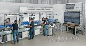
In order to meet the needs of different customers, manufacturers are facing challenges brought about by the increase in production varieties and the decrease in batches. These challenges are mainly the impact on the final assembly stage of the product manufacturing process. Assembly process planning must take into account various requirements and boundary conditions, make appropriate adjustments to the changes of new products, and always pay attention to the system configuration status of the assembly system. In addition, the designed assembly system should be able to assemble changing products, such as the physical network assembly system described in this article and its assembly process planning (Figure 1).

Figure 1 In a network physical installation system that adopts a modular and reconfigurable structure, each assembly station will be linked together through an integrated transmission system
Product assembly task description
Whether in the virtual assembly process planning or in the subsequent equipment operation, the description template will be used to describe the product, process and production equipment in general. Based on this template, during assembly process planning, it is necessary to ensure the compatibility of products and equipment by describing product requirements, production equipment capabilities, and assembly basic tasks, subtasks and parameter templates to complete the required assembly process . The basic tasks of assembly include manipulation, configuration, debugging, auxiliary procedures and special procedures. Each module is responsible for completing a specific task, so that the description of product requirements and the assignment of assembly system modules will be completed together with the subtasks. The detailed description is achieved by various parameters. The planning and control of the assembly process will also be described. Since both planners and assembly modules at the operation level can interpret the descriptions of selected tasks and parameters, the unified semantic description of assembly tasks and assembly and operation level parameters will promote the development of information universality.
Virtual evaluation of product assembly
At the planning level, virtual adjustments are made to product requirements and production equipment capabilities by starting a capability-oriented description template, so that product assembly can be virtually evaluated. The information obtained from the evaluation will then be exported as the assembly memory, so that the product assembly can be completed according to the specific indicators in the plan.
The capability-oriented task description will be used as an example to describe the Torx screw tightening process and the modules involved in the two assembly processes. First transport the screws in place, and then tighten them with a specific torque.
In addition to the description of product requirements, the capabilities of modules must also be defined with modular thinking. The flexible, variable and reconfigurable assembly system can adapt to changing frame conditions. By changing, combining and removing various functional components, the assembly system can be set up according to the exact product, capacity and technical requirements.
In order to be able to flexibly control different modules, the traditional field program control system will not be used, but a controlled event processing system will be used. Here, events related to the assembly steps required for the product and the specific product will be activated.
The handling of events and the control of different modules of the assembly system are all done through a proxy server. These proxy servers have different interfaces to realize the communication and control of different modules. The assembly memory data will first be used in an agent-based control system in a standardized form, and will be sent to the assembly module to be controlled after being processed by a suitable formatting program. Because different interfaces can be used, such as TCP/IP or OPC, and the correct form of usable data can be obtained through the integrated formatting program and sent out, it can realize the two-way exchange of information between different systems.
Each module has an interface and independent logic as an embedded system, so that parameters can be set to control these modules according to the needs of the task. The required semantics are stored in the control system. In the system where the mechatronics module is located, people will get assistance in different ways, but they still need to accept them to complete various tasks.
The network physical assembly system consists of four modular stations
The cyber-physical assembly system embodies the industrial environment required by the research project SmartF-IT, which was jointly created with its partners. The partners are Bosch Rexroth and the German Artificial Intelligence Research Center (DFKI Saarbrücken). This kind of assembly line is equipped with a variety of small control units. The control unit has a split box and an electronic movement. It consists of four assembly stations and three converter modules. These assembly stations are established using standard components and have a basic structure equipped with the same standardized interfaces and distributed control system. The integrated transmission system connects these stations to each other.
In the assembly process, the workpiece carrier device is used to complete the transportation of products between stations. This kind of workpiece carrier device is affixed with RFID electronic tags. The tag is linked to the virtual assembly memory of different products from the beginning, so that the stored virtual assembly memory and each process step can be activated through a specific RFID ID in each subsequent station. The transmission module of each station has its own control system, which is connected with the RFID reader and positioning unit (PE) (Figure 2).

Figure 2 The transmission module is equipped with its own control device.It is connected with RFID reader and positioning unit
After the specific RFID ID is read, it will be transmitted to the proxy server. The proxy server is responsible for checking the assembly steps that need to be executed in the virtual assembly memory, and determines whether the steps can be completed at this assembly station. When the assembly station needs to perform assembly steps, the positioning unit PE fixes the workpiece carrier device to the assembly station, so that the product can be assembled. When this assembly station no longer needs to perform assembly steps, the workpiece carrier device will be transferred to the next station.
Description of the ability-oriented assembly system
In the current system configuration state, the upper bearing bush provided by the first station will be transferred for the assembly process. The transmission process is through the Pick-by-Light system. Workers can get signals from the system and learn the component type from small molecule carriers (Figure 3). In addition, machine tool workers can obtain work instructions from the displays of each assembly station. At the same time, the transmission module is equipped with a control device with set parameters, and the auxiliary module is equipped with independent logic. The proxy server will set different parameters to control these modules according to product changes, and disperse them for processing.

Figure 3 The first station will transmit different components according to different products (with the help of Pick-by-Light system) and assemble them
The second station will provide corresponding electronic accessories according to different products and assemble them. The Pick-by-Laser-Light system will be used as a transmission module. The system can read the electronic tags that have been positioned from small molecule carriers, use a 3D camera to record the clamping process, and display the corresponding KLT (assembly component) through a laser projector. As in the first station, the lower bearing used to lock the product will be transported in place via the Pick-by-Light system at the third station. When the torque of this station is monitored, the wireless electric screwdriver will tighten some electronic components and the lower bearing bush.
During this process, the position of the tool center point of the screwdriver can be determined by the positioning system. The center point will only be aligned with the preset screw, so that the torque can be set at an accurate position. The recording and monitoring of the tightening process will be carried out automatically. The manipulator will select suitable screws from the screw box according to different products, and then pass them to the staff (Figure 4).

Figure 4 Cooperating with the manipulator to complete the screw transmission.The manipulator selects the appropriate screw and sends it to the staff
The assembly system design and the modularization of general information can more effectively design the assembly system planning process. Capability-oriented task description is the focus of assembly process planning and operation. In the planning process, after the virtual guarantee of the assembly process, the assembly memory for the product will appear. This memory can be used to assemble different products through a decentralized and controlled assembly process. The description of unified semantics on two levels constitutes its foundation. In the virtual model, the assembly process planning will not be affected by the system configuration status, so that the data in the planning process can be used to directly assemble different products.
[ad_2]


