Multi-robot system for mine accident search and detection based on wireless sensor network
[ad_1]
In recent years, the demand for coal in my country has been increasing year by year, coupled with the lack of investment in safety over the years, leading to frequent mining accidents, causing serious losses to people’s lives and property. The most serious mining accidents are gas explosion accidents. When an accident occurred, rescue experts were unable to make timely targeted rescue plans due to the lack of necessary on-site environmental information; rescuers often need to go through a long period of forced ventilation and exhaust the poisonous gas before entering the accident site for investigation and rescue. This delayed the precious first rescue time. Therefore, it is necessary to develop a practical and reliable search-and-rescue robot that can replace rescuers in the underground to perform search tasks in the first time, and feed the searched information back to the rescuers. This research is of great significance to improve the emergency rescue capability of coal mine accidents, reduce casualties, and rescue decision-making. It also opens up a brand-new field for the research, application and promotion of robotics.
1 Working principle of search and detection multi-robot system
In order to solve the problems of underground complex environmental information monitoring, personnel search and positioning, and remote communication in mine accidents, this paper establishes a search and detection multi-robot system based on wireless sensor network. The system adopts a powerful parent robot and several child robots to form a parent-child architecture. The parent robot is the main body for obstacle crossing and detection, and the small child robots are used as communication and monitoring nodes along the way. The robot system must effectively traverse obstacles, reach dangerous and disaster sites, collect (gas, fire, and water) information and transmit the information to rescuers outside the well. Therefore, it is necessary to focus on the obstacle crossing ability, communication ability and sensing ability of the robot system. .
The underground search and detection of the multi-robot system is mainly aimed at 4 types of terrain environments: ordinary rough ground; relatively high obstacles relative to the robot body; there are obstacles up and down or even left and right, only one narrow open space; relatively long compared to the robot body Cracks. The first two types of obstacles require robots to have strong terrain attachment capabilities. Tracked robots will be more effective than wheeled robots. Generally, the larger volume (cross-section) of a single tracked mobile robot restricts its entry into narrow spaces and longer spans. Big crack. Therefore, it is necessary to construct a parent robot that is hinged by multiple crawler configurations and multi-joint bodies. This configuration enhances the robot’s ability to climb and traverse obstacles, and at the same time improve the speed of the entire system into the roadway; at the same time, the sub-robot adopts Two-wheel independent drive plus a bouncing foot method to reduce the size and facilitate deployment and have a certain local obstacle-climbing ability to build a sensor network and adjust the performance of the entire network.
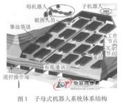
The entire robot system solves the difficult problem of crossing obstacles to enter the deep part of the tunnel. At the same time, the parent robot itself carries and configures the child robots as wireless communication nodes as needed to build a multi-hop communication network, which builds a robust platform for underground communication. The wireless communication between the child and mother robots through the relay node not only further expands the detection range, but also can dynamically monitor changes in the roadway environment through the sensor function of the node robot. The architecture of the robot system is shown in Figure 1.

2 Multi-robot system structure and obstacle crossing function
2.1.1 Structural composition of the parent robot
The parent robot is an independent and complete individual, with walking, obstacle crossing, detection and simple rescue functions. The developed parent robot is made up of articulated multi-joint bodies and consists of 5 units. Each unit has a different function. The units are connected by hinges, which can adapt to very complex terrain conditions and realize control, sensing and Communication function. The overall structure is shown in Figure 2. Each unit is equipped with its own motor and reducer, and the driver is used to independently drive its own movement. The ends of the head unit and the tail unit are equipped with foldable flexible arms, and the front end of the arms is equipped with a camera, which can be flexibly adapted to narrow passages. The control sensor unit contains a main controller based on an embedded motherboard, various motor controllers, a variety of sensors, and radio frequency transceivers. The carrying unit has a door that can be opened and closed and is equipped with multiple small robots. The power supply unit carries a large lithium polymer battery to supply power to each module.

2.1.2 Analysis of the obstacle crossing performance of the parent robot
Coal mine explosions will cause a large amount of coal to fall. According to coal quality analysis in various coal mines in my country, the fragments after the explosion are generally no more than 300 mm. Therefore, robots are required to climb over 300 mm obstacles made of fragments and can cross no wider than 600 mm. The trenches are adapted to the extreme unstructured environment formed by various objects after the destruction of the coal mine.
The main body of the mother robot developed for this obstacle crossing requirement mainly includes a multi-layer crawler robot unit and a connecting hinge.

(1) Multi-layer crawler robot cell. The robot adopts a multi-layer crawler structure, which is conducive to generating friction and driving forward. The 5 units of the robot use 3 types of crawler modules: The head unit and the tail unit are driven by a single motor to drive the double-layer four-tracks synchronously (Figure 3); the carrying unit uses dual motors to independently drive the left and right crawlers. The cabin and the door can be lowered to release the sub-robot; the other units adopt body modules (Figure 3), which are driven by dual motors left and right to independently drive double-layer crawlers and side crawlers. The 4 crawlers are driven by a motor, which is convenient for steering and propulsion.
During the advancing process, the single-layer crawler will roll the obstacles from the front and above to the bottom of the crawler to cause further obstacles, while the double-layer crawler rolls the obstacles backwards and advances in the way of “digging”, so it can drill through narrow spaces. When advancing in a complex curved roadway in the underground, the contact between the side crawler and the bottom and side of the roadway is beneficial to boost and turn. When the robot car body tilts greatly and the lower crawler cannot adhere to the ground well, the contact and relative movement of the side crawler and the bottom surface of the roadway can play a role as a booster; when there is a relatively large turn, the side crawler and the side of the roadway The contact not only avoids the car body from jamming, but also assists turning with greater driving force.
(2) Hinge structure. The adopted two-degree-of-freedom active hinge can lift its front unit, thereby overcoming obstacles up to 2 joint lengths, or crossing longer cracks relative to the robot body; controlling the hinge through the clutch can also be transformed into passive, allowing The robot body passively adjusts its posture according to the irregular terrain, so that the track can effectively cover the ground and adapt to the terrain flexibly.

2.1.3 Structural composition and bounce analysis of the round-jump composite sub-robot
The sub-robot adopts a wheel-jumping composite structure, which is mainly composed of wheeled motion components and bounce motion components. Its basic design idea is: the robot two-wheel drive in a flat environment to move to the target address; when encountering obstacles or ditches, control the bounce mechanism to make The robot crosses the obstacle in an appropriate posture. The robot wheeled motion component is composed of two independent driving wheels, and the structure of the bouncing motion component is shown in Figure 4.
The bounce assembly is mainly composed of 5 parts: a reduction motor, a release mechanism, a five-bar bounce mechanism, a pull rope, and an adjustment mechanism. When the geared motor rotates forward, the reel is driven by the one-way bearing and the complete gear, and the length of the five-bar mechanism pull rope is changed to adjust the spring tension and the energy storage of the five-bar mechanism; The release reel is driven to the bearing and the toothless gear, the spring tension is fine-tuned and the pull rope is released, and the five-bar bounce mechanism interacts with the ground to achieve bounce. The ratchet and pawl respectively play the role of locking the release mechanism and the adjustment mechanism at any position. The continuous rotation of the adjustment mechanism can adjust the energy storage of the spring to the utmost extent, and the release mechanism can be released at any position and can conveniently realize the control of the bounce. The overall size of the robot is <110 mm × 150 mm, and the total mass is 1112 kg. In the bounce experiment, when the horizontal tension spring of the five-bar mechanism uses 4 springs with an elastic coefficient of k = 112 N/mm, the measured bounce height of the robot is 75 mm. Reservation location. 3 Multi-robot system control and communication
3.1.1 Multi-robot system control integration
The mother robot uses a high-reliability embedded motherboard as the main control computer to complete the functions of moving parts driving, communication, sensor information collection, data processing, image and sound collection. The sensor uses digital output and communicates with the computer via a unified RS232 interface.
The functional composition of the sub-robot includes a motion module, a sensor module, a radio frequency communication module, a processor module, and an energy supply module. Among them, the processor module is the core of the entire system, using an ARM-based embedded controller to coordinate and control the functions of the motion, sensing, and communication modules.
The communication between the parent robot and the child robots, and each child robot is realized through a multi-hop communication link built by the parent robot and each child robot. The information collected by the sensor is fused and compressed by the embedded system, sent to the communication link through the radio frequency module, and transferred to the base station side by layer.
3.1.2 Multi-hop communication network structure
There are two main structures in wireless sensor networks: centralized control structure and distributed structure.The centralized structure requires a powerful and centrally located master node, which is difficult to implement underground; the distributed structure requires a lot of construction and maintenance costs, and is prone to problems such as flooding.[ 5 ] . After analysis, the coal mine’s main roadway has a long and narrow structure; although the working face roadway has a large plane space, the communication barrier is still the barrier caused by the intricate roadway wall. Therefore, the establishment of a distributed chain-like network structure composed of multiple robots can well solve the problem of multi-hop communication in narrow and long roadways. At the same time, in order to ensure the reliability of the chain structure, a redundant robot is set up between the effective communication distance of the two robots to solve the life and reliability problems caused by the unique node, and form a distributed chain network with redundant nodes. structure.
This network structure is composed of base stations, child robot nodes, child robot redundant nodes, and parent robot nodes. In the configuration of the network, the base station is set at the deepest part of the roadway reachable by humans, so as to enter the mine as deep as possible, and connect to the control center by cable as long as possible to ensure the reliability of energy and communication; the mother robot passes The carrying compartment carries the child robot to walk. When the parent robot detects that the wireless signal with the base station or the upper-level node has attenuated to a specified threshold through RSSI (Received Signal Strength Indication Method), the parent robot opens the carrying compartment door and releases a child robot. Do communication relay. By setting the threshold reasonably, there can be redundant nodes in the communication distance of normal nodes.Use load balancing mechanism and minimum energy principle for network resource planning and energy saving control[ 6 ], Make redundant nodes and working nodes work alternately, and move appropriately according to the energy situation, which can guarantee the network survival time to the greatest extent. This kind of multi-communication node multi-hop networking mode is conducive to the expansion of the network, and is especially suitable for communication in underground curved roadways. Adding sensing elements to each communication node can also dynamically monitor the gas and temperature changes in the entire tunnel.
3.1.3 Communication protocol
In order to improve throughput and reduce the complexity of routing design, the entire chain network adopts a routing strategy that acts as the master node in the order of node IDs.
Before configuration, the ID number of each node is determined by program solidification. After the parent robot is configured in the order of ID, the robot system forms a chain structure network arranged in the order of ID.[ 7 ] . In the normal operation of the network, each node is in the monitoring state, and the main robot initiates a communication request (control frame) to the next node in the reverse order at regular intervals. For the control frame received by a normal node, if the destination ID in the message matches with itself, this node becomes the master node, switches to the receiving mode, and receives the information (data frame) from the previous master node; when it receives all the information, the previous master The node enters the monitoring state, and the master node starts to look for the next node in the reverse order as the master node. If the node with the destination ID does not respond, the master node will automatically subtract 1 from the destination ID number to find a node with a smaller ID number, and the node with a smaller ID number will become the master node after receiving this request. If the node cannot monitor any information from the superior node within a few communication cycles, it will automatically adjust its position to move closer to the superior node. The data frame is delivered to the base station in this multi-hop manner from node to node, and the entire communication process ends.
In addition, taking into account the requirements of certain roadway information monitoring, sometimes it is necessary to allow ordinary nodes to become the master node, actively initiate communication, and send some emergency information. For example, in an emergency, ordinary nodes must immediately send alarm information (message frames) back to the base station in order to take corresponding measures.

As mentioned above, the information frame for communication and transmission between the master node and the ordinary node has three formats: control frame, data frame and message frame[TheformatsofthethreetransmissionframesareshowninFigure5Amongthemthecontrolframeandmessageframearetransmittedbythemasternodeandreceivedbytheordinarynode;whilethedataframeistransmittedbytheordinarynodeandreceivedbythemasternodeThecontrolframeisdividedinto4sections:thefirstsectionuses4bitbytestodescribethetypeoftheframe;thesecondsectionisthedestinationIDnumberforinformationtransmission;thethirdsectionisthecontrolinformation;thefourthsectionisthechecksectionThedataframeisdividedinto5sections:Thefirstsectionisusedtodescribethetypeoftheframe;thesecondsectionisthedestinationIDnumberoftheinformationtransmission;thethirdsectionisthedatalengthinformation;thefourthsectionisthedatasectionandthelengthisdeterminedbythedatalengthparameterDecided;ThefifthparagraphistheverificationparagraphThemessageframeisalsodividedinto4sections:thefirstsectiondescribesthetypeoftheframe;thesecondsectionisthedestinationIDnumberoftheinformationtransmission;thethirdsectionisthealarminformation;thefourthsectionisthechecksection[。 3种传输帧的格式如图5 所示,其中,控制帧和消息帧由主节点发射,普通节点接收; 而数据帧由普通节点发射,主节点接收。 控制帧分为4段: 第1段使用4 bit的字节用来说明帧的类型; 第2段为信息发送的目的ID号; 第3段为控制信息; 第4段为校验段。 数据帧分为5段: 第1段用来说明帧的类型; 第2段为信息发送的目的ID号;第3段为数据长度信息; 第4段为数据段,长度由数据长度中的参数决定; 第5段为校验段。 消息帧也分为4段: 第1段说明帧的类型; 第2段为信息发送的目的ID号; 第3段为报警信息; 第4段为校验段。
4 Multi-robot system sensors and interface modules
4.1.1 High-performance downhole gas and environmental detection sensors
Downhole search and detection need to ascertain multiple indicators including methane (CH4), carbon monoxide (CO), oxygen (O2), temperature, humidity and wind speed. In order to reduce the size and facilitate integration, MEMS process sensors are selected, and the sensors are integrated and intrinsically safe to make them have the characteristics of small size, high integration, good stability, and fast response, which are suitable for downhole detection needs. This text has carried on the unified interface design to the CH4, CO, O2 sensor based on MEMS craft, it is convenient to call as the module.
Temperature sensing uses digital temperature sensor chip LM75, which uses 12-bit digital signal output and integrates I2C serial interface, which is convenient for application and does not require peripheral circuits. In this paper, the mother robot adopts the independent ultrasonic sensor TCT4010F/S, which judges the distance to the surrounding obstacles through the round-trip time from the transmission to the reception of the ultrasonic wave, so as to ensure that the robot has a good obstacle avoidance ability. The robot uses the dual-axis acceleration sensor ADXL203 and the angular velocity sensor ADXRS150 to determine its own pose at any moment. The dual-axis acceleration sensor calculates the pitch and roll angles based on the components of the gravitational acceleration, and the angular velocity sensor is used to measure the azimuth angle. The measured signal is sent to the sensor module for further processing through A/D conversion.
4.1.2 Sensor interface module that can be flexibly configured
The multi-sensor module is an important part of the robot’s perception of its own information and external information. When targeting the complex underground application environment, multiple robots carrying different sensors form a robot system to coordinate work for environmental investigation. Therefore, it is necessary to build a hardware system that can be flexibly compatible with multiple sensors, and configure the required sensor types according to user requirements.

FPGA implements hardware interface circuits in software, which is convenient for interfacing with various sensors. It reads user configuration data in EPROM into the on-chip programming RAM, and completes the configuration of its own state with these data. The hardware has strong flexibility in connection. When the FPGA function needs to be modified, different circuit functions can be generated only by modifying the programming data in the EPROM. The sensor processing circuit of this text selects Cyclonee series FPGA device of Altera Company. The hardware composition principle is shown in Figure 6. Cyclone FPGA devices include N IOS soft core CPU, phase-locked loop, and interface between the CPU and external devices; EPCS1 is used to configure the FPGA when power is on; EEPROM is used to store sensor calibration parameters; AD7888 Used to collect sensor signals, 8 single-ended inputs, serial interface SPI; The currently selected sensors include temperature sensors, ultrasonic sensors, acceleration sensors, and magnetometers.
Among them, the 32-bit CPU or N IOS soft-core processor is an embedded system microprocessor IP core with a 32-bit/16-bit bus instruction set and data channel that can be configured and constructed on demand. This part of the design uses Altera’s SOPC Builder to automatically define the system, complete the integration process of SOPC development, and add a timer to the processor to implement AD timing sampling. SP I module is used to realize the interface with serial AD. One of the characteristics of the N IOS processor is the Avalon bus, which is a simple bus protocol that connects the on-chip processor and other IP modules. It specifies the port and communication timing for the connection between the master component and the slave component.
Different from the central arbiter in the traditional bus structure, the switch structure of the Avalon bus uses slave arbitration technology, allowing multiple master device controllers to operate simultaneously, and the slave arbiter determines which master device gets access. This switch structure optimizes the data flow and improves the throughput of the sensing system.
5 Conclusion
(1) A reasonable child-mother-type multi-robot system architecture was constructed, and the mobile carrier of the parent and child robots with strong obstacle crossing ability, high mobility and terrain adaptability was designed to adapt to the extremely non-structural after the coal mine explosion surroundings.
(2) Based on wireless sensor network technology, using multiple robots to form a distributed chain-like network to achieve long-distance and stable multi-hop network communication in underground tunnels under the conditions of rock wall scattering and many obstructions.
(3) A multi-sensor interface module based on FPGA soft core is established, which can easily integrate various environment detection sensors and robot status sensors.
At present, coal mine accidents in our country are in a period of high incidence, and there is an urgent need for underground accident detection and rescue robots. Therefore, the development of practical coal mine search and detection robots and the exploration and research of cutting-edge technologies have important social significance and academic value. The future industrialization prospects are also very broad. It can be used not only for coal mine accidents, but also for earthquakes and fires. And other natural disasters and man-made accidents.
[ad_2]


