Scheme of wireless sensor network in field measurement
[ad_1]
In the field of industrial measurement, long-term, large-scale, multi-channel data measurement systems are often required. In the field of field environmental monitoring, due to the special circumstances of environmental conditions, the monitoring system is often difficult to deploy effectively due to factors such as power supply and long-distance wiring. Because of its low power consumption, self-organizing routing, and no wiring, wireless sensor networks are particularly suitable for field measurements in the industrial field.
This article will introduce a case of a wireless sensor network deployed in a coastal city in southern my country. The system can meet many industrial measurement needs after a few modifications.
The city has a large number of mountainous landforms, with a large population of urban residents, which requires a high utilization rate of land. Therefore, a large number of buildings and roads are located near the mountainous area. The rainfall in this area is high all year round, especially during the rainy season in summer, when there will be a lot of precipitation. Unstable mountainous landforms are prone to landslides after being eroded by rain, which poses a huge threat to the safety of residents’ lives and property.
Local authorities have tried to deploy too many wired monitoring networks to monitor and warn of landslides. However, because the monitoring areas are often inaccessible mountains, lack of roads, field wiring, power supply, etc. are restricted, making the deployment of wired systems It’s very difficult. In addition, the wired method often adopts the method of deploying the nearby Datalogger to collect data, and it requires a dedicated person to regularly go to the monitoring point to download the data. The system cannot obtain real-time data and is less flexible.
In this regard, after several exchanges with geographic monitoring experts and several field visits, Crossbow Company proposed a complete set of wireless solutions for landslide monitoring based on wireless sensor networks.
Basic measurement principle
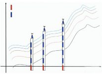
The monitoring of landslides mainly relies on the function of two kinds of sensors: liquid level sensor and inclination sensor. In areas where the mountain is prone to danger, a number of holes are vertically arranged along the direction of the mountain, as shown in Figure 1. A liquid level sensor is deployed at the lowest end of each hole, and several inclination sensors are deployed at different depths. Since the landslide phenomenon in this area is mainly caused by rainwater erosion, the depth of the groundwater table is the first indicator to identify the risk of landslides. The data is collected by the liquid level sensor deployed at the bottom of the hole and sent by the wireless network.

The movement of the mountain can be monitored by the inclination sensor. The mountain is often composed of multiple layers of soil or rock. Different layers have different moving speeds due to different physical composition and different degrees of erosion. When this phenomenon occurs, inclination sensors deployed at different depths will return different inclination data, as shown in Figure 2. After the wireless network obtains the data of each inclination sensor, through data fusion processing, professionals can judge the trend and intensity of the landslide based on this, and judge its threat.

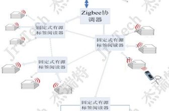
The overall system architecture is shown in Figure 3. The products used by Crossbow for this project include new Mote node IRIS, MDA300 data acquisition board, Stargate base station; MoteWorksTM software environment includes Xmesh protocol stack (IEEE802.15.4 compatible), Xserver middleware and MoteWeb visualization Management platform.
The data detected by the sensor nodes is transmitted to the base station through the Xmesh wireless multi-hop self-organizing network, or transmitted to the base station through the relay Mote. Mote is the basic node of the wireless sensor network, which is composed of a processor and an RF chip. Its size is small, so it is called “Mote”. The base station is the gateway device used to communicate between the wireless sensor network and the existing IP network.
The base station transmits these data to the central server. After parsing by Xserver middleware, users can monitor through IT system application software; at the same time, the data interface is fully compatible with the customer’s original information management system, and users can flexibly add new sensor data The original information management system can monitor the physical world information in real time through the IP network.
In actual deployment, Crossbow uses a hierarchical network architecture. The wireless sensor nodes in each target monitoring area form a subnet, and the nodes in the subnet rely on the Xmesh wireless multi-hop self-organizing protocol to transmit data to the Stargate base station in a multi-hop manner. After the base station performs data preprocessing, it sends the data back to the central server over a long distance through the GPRS network, as shown in Figure 4.

Each target monitoring area is approximately composed of 10-20 nodes (adjusted according to specific conditions), and the entire project is composed of several monitoring areas. Due to the powerful functions of Crossbow’s Xserver middleware server, the system configuration is flexible and adjustable (including sub The number of networks and the number of nodes in the network). The distance between adjacent nodes is about 20-100m, and the data collection interval can also be flexibly controlled by the central server. It can be adjusted to collect and transmit data every 24 hours during the dry season, thereby saving energy and avoiding a large amount of redundant data. In the dangerous period of the rainy season, the collection interval can be as dense as once every 2 minutes to ensure real-time monitoring and early warning functions.
The system supports two-way data transmission. All data is collected to the base station and connected to the upper IT system for data integration, which is convenient for management and query.
Sensor node
Each sensor node includes liquid level sensor and tilt sensor element, IRIS wireless sensor network node, MDA300 data acquisition board and battery pack.
MDA300 provides 8 ADC channels, 8 digital channels and I2C interface for external sensors of various types. In this project, the tilt sensor voltage output is 0~5V, and it is easy to connect to the 0~2.5V ADC interface provided by MDA300 through the resistor divider network reserved by MDA300. The liquid level sensor has a 4-20mA current output. The ideal voltage source is simulated by an external battery pack, and then 4-20mA can be converted into a 0-2.5V voltage signal that can be collected by the ADC by using the resistor divider network 124? Duplicate resistors.
MDA300 is configured as 1 liquid level sensor channel and 6 inclination sensor channels.
Relay Mote
The hardware structure of the relay Mote is exactly the same as that of the Mote, except that the sensor is not connected. Different from ordinary Mote, the relay Mote is not powered by batteries, but powered by a wired form, which is always in working condition to ensure the communication efficiency of the entire network. The relay Mote transmits the data from the node to the base station through the Mesh network. When a Mote fails, other related Motes will automatically reroute. After the fault of this Mote is eliminated, it will rejoin the Mesh network to continue working.
Base station
The base station consists of a Stargate gateway and a Mote. Stargate gateway includes Intel PXA255 main processor, Intel SA1111 coprocessor, 64MB RAM, 32MB FLASH and 51-pin interface, PCMCIA interface, CF interface.
[ad_2]


