Intelligent bus (electronic) stop sign RFID application scheme
[ad_1]
1 Overview
The traditional electronic bus stop sign system uses on-board GPS to implement vehicle stop reporting. After years of operation, three challenges are faced in practical applications:
1) Large investment and high operating cost. Each vehicle needs to invest in on-board GPS+GPRS, and a monthly SIM card communication traffic fee is required. Due to the large number of vehicles, this operating cost is high.
2) The power consumption is large, and the battery of the bus is lost, causing the entire GPS station reporting system to be paralyzed.
3) GPS cannot work accurately on rainy days.
The RFID electronic stop sign adopts active RFID technology. By installing an RFID reader on the electronic stop sign and installing an RFID electronic tag on the vehicle, when the bus passes the station, the station actively recognizes the bus RFID electronic tag data and transmits it to the control center as a report Basic data for functions such as stations.
The use of RFID electronic stop sign technology has low overall cost, stable performance, does not incur any costs, is not affected by rain and fog, and greatly reduces the operating cost of electronic stop signs.
2. System structure
The system consists of RFID vehicle electronic tags, station RFID readers and electronic stop sign backend system.
The RFID vehicle electronic tag is installed on the bus, and the bus ID information is written inside; the RFID reader is installed at the station, and is connected to the electronic stop sign main control unit through the RS485 interface or RJ45 interface, reads the vehicle electronic tag information, and passes the vehicle. The situation is judged, and the vehicle information is transmitted to the electronic stop sign master control unit, and the electronic stop sign master control unit transmits the data back to the business system platform through the 4G wireless network.

3. Program features
Based on active RFID technology, electronic tag reading is stable and reliable.
Supports vehicle direction discrimination through RFID front-end equipment, and effectively filters vehicles on the opposite lane.
Support the judgment of the driving direction of the background vehicle.
Supporting the management of bus entry and exit.
4. Introduction to the principle of vehicle driving direction algorithm
1) RFID front-end automatic identification scheme

As shown in the figure above, two readers 1, 2 and communication gateways are installed at each station. When the vehicle passes through the station, it is read by RFID readers 1 and 2 successively, and the read electronic tag data is processed through the communication gateway through the algorithm, and the vehicle entry record is output. .
The basic judgment logic principle is as follows:
When a vehicle enters the station, the reader 1 will read it first, and then the reader 2 will read it, then it can be judged that the vehicle has entered the station
If it is an oncoming vehicle, it will be read by reader 2 first, and then by reader 1. Can be filtered out.
In practical applications, the built-in algorithm of the communication gateway needs to deal with various possible situations and output the correct vehicle entry records.
2) Background judgment plan

When using the system background judgment, only need to deploy an RFID reader at the station, read the vehicle RFID electronic tag information, and send it to the business background. The business system platform judges the direction of the vehicle based on the neighboring station information and generates the arrival record.
The judgment logic is as follows:
The reader reads the electronic label
Obtain the coding information of the previous station from the background or electronic tags, and determine whether the vehicle is in the current lane or the opposite lane according to the station relationship. If it is the opposite lane, the previous stop information must be the previous stop in the opposite lane. It can be filtered out.
5. Main equipment
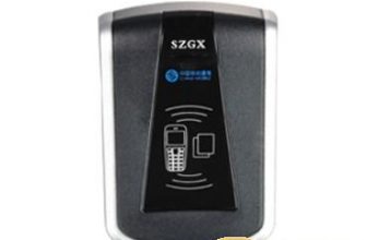
5.1. RFID reader
Model: ZCR811

Long reading distance, effective distance up to 300m
Efficient anti-collision algorithm, read more than 1000 tags at the same time
Integrated, waterproof/lightning protection suitable for outdoor application environment
Flexible wireless configuration of tags
Multiple interfaces, suitable for different applications, provide SDK and underlying communication protocol
|
technical parameter
|
|
|
working frequency
|
2.45GHz ~ 2.5GHz
|
|
Reading distance
|
150mAdjustable inside (open area up to 300m)
|
|
Recognition speed
|
100km/h
|
|
Recognition ability
|
Recognize more than 200 labels at the same time
|
|
Antenna angle
|
Orientation (vertical 70° / horizontal 70°)
|
|
Interface Type
|
WG26 / 34; RS485 / RJ45
|
|
power supply
|
DC12V / 1A
|
|
Protection level
|
IP65
|
|
weight
|
2.5kg
|
|
Operating temperature
|
-20℃ ~ +60℃
|
5.2. Vehicle label
Model: ZCT422

Use high-strength shell material, waterproof, high temperature resistance, impact resistance
Strong anti-interference, adapt to complex application environment
Long reading distance, low power consumption, anti-collision, maintenance-free
RFID personnel identification card
Model: ZCT311

Strong anti-interference, adapt to complex application environment
Integrated design, sturdy and durable
Soft pack lithium manganese battery, more than 5 years of service life, 2 years warranty
High-performance adaptive frequency modulation algorithm, cooperate with reader to achieve high data throughput
Card parameters are configured wirelessly
|
technical parameter
|
|
|
working frequency
|
2.45GHz ~ 2.5GHz / 13.56MHz
|
|
Card parameter configuration
|
Wireless interface configuration
|
|
Card number
|
ID / ICmodel
|
|
Operating mode
|
TTF
|
|
Number of channels
|
8Piece
|
|
Power consumption
|
Standby current 2uA
|
|
Battery
|
Lithium manganese soft pack battery, capacity 800mA, battery life> 5 years
|
|
Protection level
|
IP65
|
|
size
|
86 x 54 x 4.7 mm
|
|
Operating temperature
|
-40℃ ~ +60℃
|
5.4. Communication Gateway
Model: ZCM311

Efficient entry and exit judgment algorithm to accurately realize personnel entry and exit judgment
Large-capacity data storage, offline automatic data storage, online automatic upload
Multiple interfaces, supporting GPRS/3G/Ethernet data interface environment
Remote monitoring of equipment status
Built-in switching power supply, wall-mounted installation
|
technical parameter
|
|
|
algorithm
|
Built-in access judgment algorithm
|
|
power supply
|
220VBuilt-in switching power supply
|
|
Interface Type
|
WG26/34 , RS485, Ethernet, 3G, GPRS
|
|
Operating temperature
|
-20℃ ~ +60℃
|
|
Storage temperature
|
-40℃ ~ +80℃
|
|
Gateway size
|
155mm X 115mm X 34mm
|
|
Box size
|
323mm X 230mm X 65mm
|
[ad_2]


