Solution of pressure sensor based on Wheatstone bridge
[ad_1]
All types of sensors have been greatly developed in the past few years, and compared with previous products, more accurate and more stable. Sometimes, these sensors are not easy to use. Designers of adjustment circuits for these sensors often find the development of such circuits somewhat troublesome. However, with only a small amount of basic knowledge and the use of new online sensor design tools, many challenges in this process can be easily solved.
Although there are many types of sensors on the market, pressure sensors are the most common. Therefore, this article will discuss the basic working principle of the Wheatstone bridge pressure sensor, and the processing circuit used to convert the output of this bridge sensor, including offset and gain calibration.
Pressure sensor based on Wheatstone bridge
Many pressure sensors use micro-electromechanical system (MEMS) technology, which consists of 4 varistors connected by a Wheatstone bridge structure. When there is no pressure on these sensors, all resistance values in the bridge are equal. When an external force is applied to the bridge, the resistance of the two opposing resistors will increase, while the resistance of the other two resistors will decrease, and the increased and decreased resistances are equal to each other.
Unfortunately, things are not so simple, because the sensor has offset and gain errors. Offset error refers to the output when no pressure is applied to the sensor; gain error refers to the sensitivity of the sensor output relative to the external force applied to the sensor. A typical sensor generally specifies an excitation voltage of 5V and a nominal full-scale output of 20mV/V. This means that when the excitation voltage is 5V, the nominal full-scale output is: 20 mV/V × 5 V = 100 mV.
The offset voltage may be 2mV, or 2% of full scale; the minimum and maximum full scale output voltages may be 50mV and 150mV, or ±50% of the nominal full scale.
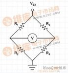
Assuming that two resistors are connected in series to form a resistor string, the node voltage between the two resistors is half of the resistor string voltage because they are of equal value. If the value of one resistor is increased by 1% and the other resistor is decreased by 1%, the voltage at the node of the two resistors will change by 1%. If two resistor strings are connected in parallel, as shown in Figure 1, the resistance of the lower left resistance and the upper right resistance are both reduced by 1%, and the other two resistances are increased by 1%, then the voltage between the two “middle” points Change from zero difference to 2% change. This configuration of two parallel branches is called a Whiston Bridge.

Figure 1: Wheatstone bridge driven by excitation voltage VEX and differential output voltage V
If we do not understand the true relationship between the offset and the sensor output voltage and pressure, we can only roughly estimate the amount of pressure exerted on the sensor. This means that sampling and calibration methods are needed to obtain better accuracy.
Fortunately, the offset and full-scale error of a given sensor are quite stable over time, so once the sensor is calibrated, it may not be necessary to change the calibration coefficient during the life of the sensor to meet the accuracy requirements. Of course, the system usually needs to be calibrated every time the power is turned on.
The basic signal conditioning circuit consists of an instrumentation amplifier and an analog-to-digital converter (ADC). The instrumentation amplifier amplifies the small output voltage from the sensor to a level suitable for the ADC, and then the ADC converts the amplified sensor output voltage to digital, and then passes it to the controller or DSP for processing (Figure 2). The instrumentation amplifier can be used to avoid bridge overload, and this overload will change the sensor output voltage value.

Figure 2: Basic pressure sensor adjustment circuit
The full-scale output of the sensor is the maximum input, which can be seen at the input of the amplifier. When the sensor output is at full scale, the ADC input should be close to its full scale value, which is usually the ADC reference voltage VREF. The required gain of the amplifier is:

Where VREF represents the reference voltage of the ADC, and “Sensor FS” is the full-scale output value of the sensor. Assuming that the resistances are perfectly matched, then the gain of the instrumentation amplifier is equal to:

Challenges to be solved
As mentioned earlier, there are two major challenges to the sensor: First, the sensor has an output offset. This offset can be adjusted by applying an appropriate voltage to the VOFF point in Figure 2, or eliminated by software after the sensor output is digitized. . If it is processed by software, then VOFF becomes 0 volts.
The problem with using software to eliminate offset is that it limits the measurable sensor range. If the offset is positive, it will limit the maximum sensor output that can be measured because the amplified sensor output may reach the ADC full scale value earlier than expected. If the offset is negative, it will not be possible to accurately measure the output level of a very small sensor, because the ADC output code will not be higher than the zero-crossing value before the amplified offset value is exceeded.
The second challenge is the range of output voltage values possible for the full-scale output of the sensor. For example, a sensor with a nominal full-scale output voltage of 100mV may have an indicator that indicates the possibility of such a full-scale output as low as 50mV and as high as 150mV.
If the full-scale sensor output is lower than the nominal value, the ADC’s full-scale range will not be used. If the full scale sensor output exceeds the nominal value, the ADC output will reach the ADC full scale output value before the sensor output reaches its full scale. In addition, if the sensor output or the amplifier itself drifts, there will be some uncertainty and imprecision in the reading.
Fortunately, current sensors are very small even with time drift. Careful selection of amplifiers can minimize amplifier drift. Therefore, the circuit gain can be adjusted in place during manufacturing and/or when the system is powered on.
One way to achieve this is to use a digital-to-analog converter (DAC) to adjust the ADC reference voltage VREF to compensate for the full-scale error of the sensor, and to use another DAC to adjust VOFF in Figure 2 to compensate for the offset error. Dual-channel DACs, such as National Semiconductor’s DAXxx2S085 (where “xx” can be 08, 10, or 12, representing the DAC resolution), will be ideal for this application. Another method is to use software to calibrate these errors after the sensor output is digitized.
The best solution to solve these two challenges is to adjust the offset and gain errors during the manufacturing process and the software calibration process at system startup. This method allows software to achieve minimum error calibration and maintain the maximum available dynamic range of the ADC.
The third problem is that single-ended ADCs usually require their input to be driven very close to zero volts to produce a zero output code. The reason for the problem is that the amplifier used to drive the ADC input cannot produce an output lower than about 50mV. This phenomenon is common even if the amplifier used has rail-to-rail output capability.
Although it does not matter that the circuit cannot provide the smallest ADC zero output code for some applications, it is a problem for other applications. For the latter, the solutions include:
Provide a negative power supply to the amplifier driving the single-ended input ADC.
Use a single-ended ADC with both a positive reference voltage and a negative reference voltage. These reference voltages can be set to a value higher than the device ground and offset the ADC input voltage accordingly.
Bias the ground of the ADC to approximately 100mV.
Offset ADC input, discard some codes at ADC output, adjust with software
Use differential input ADC.
There is a disadvantage of using a negative power supply for the amplifier driving the ADC, that is, there may not be a negative power supply in the system, and it does not seem feasible to provide a negative power supply for this amplifier alone. In this regard, National Semiconductor’s switched capacitor voltage inverter LM2787 provides a simple solution.
All ADCs have a positive reference voltage and a negative reference voltage. The difference between these two reference voltages is the so-called ADC “reference voltage”. The negative reference and the positive reference voltage define the minimum and maximum input voltages, respectively. Unfortunately, many ADCs currently define the negative reference voltage as the device ground. This is a sacrifice for integrating the ADC in a smaller package with fewer external pins.
Raising the ground level of the ADC is usually not an easy task. In addition, biasing it too high may cause output interface problems, because the logic low level of the device will be higher than the ground bias value. However, doing so has the same effect as defining the ADC negative reference voltage as a low value (maybe 70mV to 100mV).
Increasing the ADC offset and making appropriate adjustments to the ADC full-scale input value is a feasible method, but it will reduce the dynamic range used by the ADC. Doing so is equivalent to providing the positive VOFF shown in Figure 2, reducing the amplifier gain, so that the ADC input does not exceed the ADC reference voltage, and software adjustments to the ADC output code.
Using a differential input ADC is the best method. It can obtain the ADC zero output code, maintain good circuit linearity over the entire input voltage range of the ADC input, and does not need to use negative voltages in the system. In this method, the output of the differential amplifier is fed back to the differential input of the ADC without the need for a differential to single-ended amplifier circuit. So this is a perfect solution that is both simple and efficient.
[ad_2]


