Base station electricity meter electricity consumption information collection and management system plan
[ad_1]
1. The background and conditions for the establishment of the system
Communication companies have always adopted manual management for the energy consumption management of base stations. Due to the wide geographical distribution of base stations, the diversified power supply sources, the diversity of power use sites, and the shortcomings of insufficient labor, the measurement of base station power consumption has not been true. , Accurate, real-time and reliable. In addition, due to the abnormal operation of the base station caused by the power failure, the inability to receive a timely response has caused some production accidents and equipment losses. In view of the above situation, it is urgent to establish a base station remote data collection system to transmit important production data such as base station electricity consumption data and random electricity failures to the communication company management center in a timely manner through the CDMA 1X network or SMS for management and response.
1.1. Requirements for base station electric meters
Since the base station of the communication company is set up at a different time, the electric energy meter equipment used is also different. The watt-hour meters used include induction watt-hour meters, electronic watt-hour meters, and IC card watt-hour meters. The prerequisite for the establishment of this system is that an intelligent direct-reading electric energy meter must be installed. This type of electric energy meter has an RS485 communication interface, which can receive instructions through the RS485 bus and upload the current electricity consumption indicator.
Second, the composition of the system
2.1, structure description
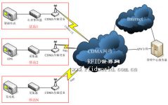
The system uses the telecom CDMA wireless network as the data transmission channel. The smart meter of each base station transmits the collected data to the embedded CDMA wireless data remote transmission device directly or through the meter reader. Embedded CDMA wireless data remote transmission equipment packages the data from smart meters or meter collectors according to the internal protocol defined by the system, and transmits them to the management center through the telecommunications CDMA wireless network via IP or SMS for processing.
2.2. Schematic diagram of structure

3. Detailed description of the functions of each component of the system
3.1 Smart Meter and Collector
A) Smart meter, smart meter with RS485 communication interface. Use Modbus protocol or other open interface control protocol. It can receive instructions and send current energy indication data through the RS485 interface.
B) The electric meter reading device, the electric meter reading device can be compatible with the control protocol used by the smart electric meter with RS485 communication interface. It can receive instructions and send the data stored in the collective copy through the RS485 interface.
3.2 Embedded CDMA 1X/SMS data remote transmission equipment
Embedded CDMA 1X/SMS data remote transmission equipment adopts mature and stable CDMA communication module, which can adapt to CDMA 1X communication network. Data can be sent via SMS and online IP. Support remote setting function. The collection time interval, transmission time and other parameters can be set remotely through SMS. Support user-defined data protocol. Able to store 100 pieces of collected information. And support historical data transmission after the network is interrupted and reconnected. Support power failure protection function. Support the point-to-point network connection function between two devices. When the IP of any one of any two devices is changed, the point-to-point network connection between the devices can be re-established. Support power alarm function. When the main power supply is interrupted, it can actively send an alarm message. UPS switch alarm function (requires additional configuration of collector). When switching from the main power supply to the UPS backup power supply, it actively sends an alarm message to remind the management center of the power switching situation.
Generator switching alarm function (requires additional configuration of collector). When switching from the main power supply to the generator backup power supply, it will actively send an alarm message to remind the management center of the power supply switching situation.
3.3 Emergency power supply module
A) Comparison of several emergency power solutions
The current emergency power solutions mainly include the following: Using base station UPS power supply, the advantage of this method is that sharing UPS backup power with the base station reduces the cost of the system, and the durability of the power supply is good. Disadvantages may affect the use of backup power in the base station itself.
Use rechargeable batteries. The advantage of this method is that it is easy to use and will not affect the backup power supply of the base station itself. The disadvantage is that the current rechargeable battery may explode and catch fire during the long-term connection with the charging device, which is not conducive to the safety of the base station equipment. Adopt solid-state energy storage device. The advantage of this method is simple and safe to use. The disadvantage is that the stored backup power is small, and it can only supply the system with power for about 1 minute to send alarm messages.
B) Selection and function description of backup power supply
This system is to better understand the working conditions of base station equipment and reduce base station failures. Both the use of base station UPS power supply and the use of rechargeable batteries will endanger the normal operation of the base station itself, so the solid-state energy storage device is chosen as the backup energy source for this system. The solid-state energy storage device can store electrical energy when the power supply is normal, and automatically switch to the solid-state energy storage device when the main power supply is interrupted, and the wireless device sends out a power failure warning message to notify the management center at the same time.
[ad_2]


