Smart home control system based on single-chip microcomputer and CAN bus
[ad_1]
1 Introduction
Smart homes emerged in Japan, Europe and the United States in the 1980s, and entered China in the late 1990s. With the development of the economy and the improvement of people’s living standards, they are gradually understood and accepted by the Chinese people. At present, there are many kinds of intelligent systems and products in China, but each system is independent of each other, the integration level is low, and there is little contact with each other. For example, building intercom systems, security systems, and automatic control systems for household appliances all have their own terminals, and there is no unified intelligent control platform. For users, this situation has increased the cost of use and the complexity of operation; for construction, it has led to repeated wiring. In response to this situation, this paper designs a single-chip computer AT89C52 as the control core, and uses the original telephone network to integrate the building intercom, security alarm and telephone remote monitoring system to form a unified intelligent control platform, and through the CAN bus The network is connected to the door phone and the management machine, which can realize the intelligent home control system of building intercom, telephone remote monitoring and alarm functions. This system is simple to operate, does not require repeated wiring, and the cost is reduced. It is a system that is truly suitable for smart homes.
2 The main composition and functions of the smart home control system
(1) Building intercom system
The building intercom adopts a community networking system. The intercom system is installed at the door of each residential unit and in the households to realize the identity verification of visitors and the intercom with the residents, as well as the function of remote control unlocking by the residents, thereby effectively preventing illegal persons from entering the residential building. .
(2) Home security system
The home security system has functions such as anti-theft, fire prevention, remote monitoring and alarm.
(3) Automatic control system for household appliances
The main function of the automatic control system for household appliances is to control electrical equipment such as household appliances and lighting. The system can realize the local centralized control of home interior lighting or household appliances, and can also remotely control the home appliances through the telephone when needed, saving energy.
3 Hardware design and implementation of smart home control system
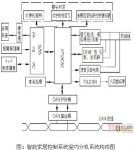
The composition of the indoor extension system of the smart home control system is shown in Figure 1. The system is mainly composed of single-chip microcomputer and its I/O port expansion part, building intercom part, security alarm part, telephone remote monitoring part, node part connected with CAN bus, keyboard and display part.

3.1 Single-chip microcomputer and its I/O port expansion part
The single-chip microcomputer selects the AT89C52 with powerful control function as the main controller, which is mainly used for signal acquisition, data processing, and control signal output. It is the core of the entire control system. Because this system requires more I/O ports, the I/O ports provided by the microcontroller itself are not enough, so the chip 8255 is used to expand its I/O ports. Among them, the PA port of 8255 works in output mode and is used for switching control of household appliances; the PB port works in input mode and is used for the input of alarm signals of various alarm detectors; and the PC port is used to extend the keyboard.
In order to meet the functional requirements of each part of the building intercom system, this system uses three I/O lines and an unlock key.
Among the three I/O lines, one is used as output to control the ringing of the intercom extension; one is used as input to detect the off-hook signal of the intercom extension; one is used to control the analog audio of the intercom extension The control relay of the signal channel allows the user to directly conduct a dialogue through the audio analog channel after it is switched on. The unlock key is set on the keyboard, and the unlock signal is transmitted to the door phone through the CAN bus, and the door phone controls the opening of the building door lock after receiving the unlock signal.
3.3 Security alarm part
The functions of the security alarm part include the input of alarm signals, local alarm, local alarm display, and remote alarm.
Alarm signals include signals from various detectors, such as window magnetic switches, door magnetic switches, passive infrared sensors, gas detectors, and fire detectors. Various alarm signals are connected to the PB port of 8255. The local alarm is that the single-chip microcomputer controls the buzzer through the I/O port to give an audible alarm, and at the same time the eight-segment digital tube display shows the alarm category. Remote alarms include remote telephone alarms and alarms to managers in the centralized control room via CAN bus.
3.4 Telephone remote monitoring part
There are three main solutions for remote monitoring: Internet-based remote control, power line-based remote control, and telephone network-based remote control. The first two networking schemes are more complex, technically difficult, and costly, and require higher technical levels of maintainers. The telephone network is a communication network with mature technology, wide application and low cost. This design adopts the telephone network to realize remote monitoring. When there is an alarm at home, the user can realize remote alarm through the phone. When remote control of household appliances is required, the user can send the control signal to the single-chip microcomputer through the telephone, and the single-chip microcomputer outputs the control signal through the PA port of 8255, and drives the relay to switch the household appliances. The circuit of the telephone remote monitoring part mainly includes three parts: signal detection, analog pick-and-hook circuit, dual-tone multi-frequency DTMF signal transceiver circuit realized by HT9170 and HT9200A, and voice recording and playback circuit using ISD1420 as the recording and playback component.
3.5 Node part connected with CAN bus
This design uses the CAN bus peer-to-peer communication network to realize the communication of information between the various extensions in the smart home control system and between the extensions and the switchboard. It has the characteristics of equal status of all nodes and no master-slave nodes.
Because the main controller AT89C52 type single-chip microcomputer does not have a CAN bus controller, this design adopts SJA1000 type CAN bus communication controller and AT82C250 type bus driver to realize the intercommunication of information between the single-chip microcomputer and the CAN bus.
3.6 Keyboard display part
The keyboard adopts a 4×4 matrix keyboard with a total of 16 keys, of which there are ten numeric keys, and the rest are fortification buttons, household call intercom buttons, unlock buttons, confirm buttons, clear alarms and disarm buttons, and home appliance control buttons. It is used for the input of various control signals, call/distress signals, unlock signals, and disarm/arm signals. The display uses a 74LS164 shift register that is serially input and output to drive an 8-segment LED digital tube for real-time display of control parameters or alarm categories.
4 Design and implementation of smart home control system software
In order to make the program clear and readable and run at a high speed, the system software adopts a modular structure design, composed of the main program and related subprograms (such as keyboard scanning subprogram, display subprogram, voice prompt subprogram, dial alarm subprogram, electrical control Subroutines, etc.). The main program flow is shown in Figure 2.

The program mainly includes three modules: security alarm, building intercom and telephone remote control.
The working process of the main program is: the system is initialized after power-on and reset. After the initialization is completed, the system detects the alarm signal, the building intercom call signal and the telephone call signal respectively, and enters the corresponding processing module if there is a signal input. In the security alarm module, a delay program is set to eliminate jitter and false alarms. The delay program is mainly realized by calling the keyboard scan subroutine. If there are still alarms after the delay is completed, local alarms, alarms to the central control room through the CAN bus, and dial-up telephone alarms will be carried out in order to achieve the function of multi-point alarms and minimize the loss.
In the building intercom module, the call signal of the door phone is transmitted to the extension via the CAN bus. After the extension detects this signal, the intercom is connected to ring, and then it is judged whether to go off-hook. If there is no off-hook signal, the delay will be judged. When the resident picks up the phone, the single-chip microcomputer outputs a signal to control the control relay of the audio communication line to connect, so that the resident and the caller can talk.
During the call, the single chip microcomputer judges whether it is on-hook, and returns if on-hook, and calls the keyboard scanning subroutine if it is not on-hook, to judge whether the unlock key is pressed, and if it is pressed, it remotely unlocks through the CAN bus and the door phone. The working process of the telephone remote control program module is that when there is an incoming call, it first detects whether it is ringing 4 times, and then simulates off-hook. After off-hook, it will play a recording prompt to enter the password. If the password is incorrect, it will simulate on-hook; if the password is correct, it will play a recording prompt to enter the serial number of the electrical appliance to be controlled, and then detect the control signal returned by it, and call the electrical control subroutine to control the on-off of the household appliance, and then simulate on-hook after completion. .
5 concluding remarks
The smart home control system designed in this article makes full use of the powerful control functions of the single-chip microcomputer and the outstanding features of the CAN bus, such as flexibility and convenience, high reliability, high communication rate, low price, and easy networking. It also combines with the existing public telephone network to provide smart The relatively independent systems in the home are integrated to realize the functions of building intercom, telephone remote control, and multi-point alarm. CAN technology is a new control network technology, combined with the existing mature public telephone network, will gradually show its unique advantages in the application of intelligent communities.
[ad_2]


