Design of Automatic Stop Announcer for Bus Based on RFID
[ad_1]
RFID technology has been widely used in the Internet of Things. It is a non-contact automatic identification technology that automatically identifies target objects and obtains relevant data through radio frequency signals. The identification work does not require human intervention. The designed RFID-based automatic bus stop announcer system is composed of a voice module, an infrared module, a temperature and humidity module, a single-chip microcomputer and an RFID module. It collects and confirms the location information of the bus, and measures the temperature and humidity in the car and the number of passengers in the car. Realize intelligent station announcement automation, reduce the driver’s work intensity, and improve the safety of vehicle operation.
In the current unmanned ticket vending vehicle system, the bus stop reporting requires the driver to manually manipulate the stop reporting button. The traditional manual push button to announce the stop can no longer meet the requirements of the bus system, and there are often false alarms, omissions, or even non-reporting, which brings great inconvenience to passengers. Manual stop reporting is of low intelligence and complex buttons. It not only requires the driver to be proficient in operating the stop reporting device, but it also poses potential hazards to the safety of public cars due to the fact that the vehicle is still being driven at the same time.
1 In order to solve this problem, this paper combines a single-chip microcomputer, voice chip, and RFID module to propose a design scheme for a bus station reporting system. Design and realize the function of automatic bus stop announcer, that is, according to the RFID recognition result, the single-chip microcomputer controls the voice chip to announce the station according to the stored station name, and realizes the automatic station announcement when the bus enters and exits, the intelligent processing of vehicles getting on and off the bus, and sending in the car Air information function, so as to truly realize the intelligentization of bus stop announcement.
2 The overall design of the system
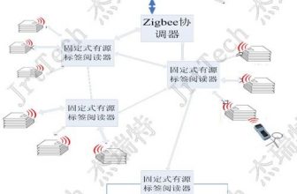
The overall design of the system is shown in Figure 1. The system is composed of a voice module, a single-chip microcomputer and an RFID module. The system determines the location of the vehicle through RFID, and transmits the signal to the single-chip microcomputer through the wireless module, and then the voice module reports the station.
2.1 RFID site identification module
This module realizes the function of RFID electronic tag identification and acquisition of related information at the bus station. Register with the electronic tag of each bus stop. Due to the uniqueness of the RFID electronic tag, the system can only accurately identify and report to the station after identifying the station. Through the identification of the electronic tag code, the station information is obtained, and finally sent to the RFID station reporting module.
2.2 RFID station reporting module
After receiving the information sent by the bus station, compare whether the station is a station in the bus route, obtain the relevant station information from the system, and send a signal to the voice broadcast system after confirmation, and the voice module will play the sound.
3 Principles of system hardware structure
3.1 On-board hardware
, The vehicle-mounted equipment is composed of a voice power amplifier circuit, a serial port communication interface, a radio frequency transceiver circuit, a temperature and humidity measurement module, and a voltage stabilizing circuit. The temperature and humidity measurement module uses the single-bus digital temperature sensor DS18B20 (temperature measurement range -55~+125 degrees Celsius) in the car to measure the temperature in the car; the humidity sensor CHR01 measures the humidity in the car; the infrared module detects the number of people getting on and off the car to get the total number of passengers in the car .
3.1.1 Humidity sensor CHR01
The humidity sensor of this system uses CHR01, which uses a functional polymer film coated on a ceramic substrate with conductive electrodes to form a sensitive component whose impedance changes logarithmically with relative humidity. The conductive mechanism is that the presence of water molecules affects the polymer film. The mobility of internal conductive ions has the characteristics of stability, low drift, high precision, fast response characteristics, high reliability, and good water resistance.
3.1.2 Temperature sensor DS18B20
The DS18B20 digital temperature sensor is easy to wire and can be used in many occasions after being packaged, such as pipeline type, threaded type, magnet adsorption type, stainless steel package type, and various models, such as LTM8877, LTM8874 and so on. Mainly change its appearance according to different applications.
3.1.3 ISD4004 voice chip
The voice prompt system uses the ISD4004 series produced by Winbond in the United States as the prompt output voice chip ISD4004 series. The working voltage is 3V, and the single-chip recording and playback time is 8 to 16 minutes. The sound quality is good. It is suitable for mobile phones and other portable electronic products. The chip adopts CMOS technology, including oscillator, anti-aliasing filter, smoothing filter, audio amplifier, automatic noise suppression and high-density multi-level flicker storage display. The chip design is based on that all operations must be controlled by a microcontroller, and the operation commands can be sent through a serial communication interface (SPI or Microwire). The chip uses multi-level direct analog storage technology, and each sample value is directly stored in the on-chip flash memory, so it can reproduce voice, music, tone and effect sound very realistically and naturally, avoiding general solid-state recording circuits Quantization noise and “metallic sound” caused by quantization and compression.
3.2 Site-side hardware
The platform-side hardware is mainly composed of transmitting code control circuit, LED electronic circuit, radio frequency transceiver circuit and voltage stabilizing circuit. The radio frequency transceiver circuit sends the electronic tag information and accepts the information sent by the vehicle; the LED electronic circuit displays the information sent by the vehicle to the platform.
LED display: The LED display module uses 1602LCM character liquid crystal display. The character generation memory (CGROM) inside the 1602 liquid crystal module has stored 160 different dot matrix character patterns. These characters include: Arabic numerals, uppercase and lowercase letters of English letters, commonly used Each character has a fixed code.
4 Principles of system software structure
The system software is written in C language and can be divided into RFID electronic tag information, which is parsed module to achieve information acquisition and identification functions; bus state judgment module and state-corresponding execution program module to achieve information processing and processing functions. LED display and voice output module realize information output function.
It is a simple flow chart for the function of obtaining, identifying and executing the RFID electronic tag information of the bus. If the RFID signal is not received or the electronic tag is “0000”, the instruction is not executed; if the RFID signal is received, analyze whether the changed station belongs to the bus The planned route of the car, if it is, the voice chip will be activated to announce the stop; if it is not, no instruction will be issued.
5 concluding remarks
According to the design plan of this article, the automatic stop reporting and platform LED display functions have been completed, and the automation of the bus stop reporting system has been successfully realized. The inaccurate bus stop reporting can be solved, providing a reliable and cost-controllable bus for the public transportation system. The multifunctional automatic station reporting system can display the information of the number of people in the vehicle and the temperature and humidity on the platform in time. If the wireless network or wired network is further used to transmit the vehicle site data to the public transportation management department or the traffic command department, real-time monitoring of the bus operation status can be carried out.
[ad_2]


