[ad_1]
1. Background
Railway level crossings are the intersection of railways and highways, and are important facilities for safe railway operation. With the development of railways, the density of crossings increases, and the risk of accidents increases as the railway speeds up. Safety production is the eternal purpose of railway transportation, and crossing safety is an important part of railway traffic safety. Embedded system is a kind of system software with a wide range of uses in the field of industrial control. It has a familiar and friendly user interface, a unified programming interface, and a powerful communication function. It has become the preferred operating system in the modification of the automatic alarm system at crossings.
The automatic crossing alarm system has a friendly interactive user interface and high safety performance. The staff can see the status of the crossing through the computer display screen when they are indoors. When a car approaches the crossing, pedestrians can get it through the crossing signal and voice speakers. For train passing information, the staff can see the train alarm information through the display and the function of automatically alarming when the external equipment fails.
2. Working principle and performance index
1. Working principle:
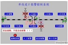
Install four magnetic pedal switches in the upper and lower directions of railway lines with level crossings. Take the upward direction as an example. The setting method of the four pedals is as follows: Set three close magnetic pedal switches at a position 800-1000 meters from the train approaching the crossing. (T1, T2, T3), set a clear magnetic pedal switch (T7) at a position 100-200 meters away from the crossing. The setting method of the downstream direction is opposite to the same position as the upstream method. False alarms may occur when railway workers work or when pedestrians crossing the railway unintentionally touch the pedal switch to produce action; when the magnetic pedal switch fails and is not replaced in time, false alarms may occur. These are not to be ignored in the crossing alarm system. The problem. Therefore, three pedal switches are set in the direction of approaching the crossing and redundant technology (two out of three) is adopted. When the train passes through the three approach pedal switches, the arrival of the train is confirmed only when two or more pedal switches operate at the same time. Minimize the occurrence of false positives and false negatives. When the train approaches the crossing and passes through the three pedal switches, the system starts to count the number of axle pairs of trains entering the crossing. At the same time, when the train passes the clearance pedal switch, the system also counts the number of axle pairs of the train. When it matches the number of axle counts entering the crossing, it indicates that the train has cleared. When the train arrives, the white light of the crossing signal is off, the red light is flashing, and the horn (or voice alarm) is sounded. At the same time, the train running status is displayed in animation on the indoor display. When the train is cleared, the alarm is cancelled, the red light is off and the white light is on. The status of each pedal switch, signal lamp filament and horn are displayed on the screen. When pedal failure, filament disconnection, speaker disconnection and other faults occur, the alarm system will automatically give a fault prompt; at the same time, it will record the start time of each alarm, The end time, the occurrence time and recovery time of the fault, etc. (User interface and layout of pedal switch[T1至T8为踏板开关]see picture 1)

Figure 1 User interface and pedal switch layout of single-track crossing alarm control system
2. Performance indicators of the crossing alarm control system
Host working environment: temperature 0℃-40℃; relative humidity below 75%; AC220±30V.
The distance of the train approaching the section is ≤1200M.
Adapt to train running speed: 2Km/h-160Km/h.
The train enters the approaching section for 3 seconds (±1 second) and the alarm starts (determined by the position of the pedal).
When the crossing signal is in the non-alarm state, the white light is on and the red light is off.
When the train enters the alarm range, the crossing signal machine starts to alarm, the white light is extinguished, the two red lights flash alternately, and the speaker emits an alarm sound.
The flashing frequency of the red light is 60±5Hz.
The sound emitted by the speaker can be set as a language alarm or a bell alarm, and it can support the broadcast function.
Working environment of magnetic probe and crossing signal machine: temperature -40℃-70℃; relative humidity below 95%.
Three, system design
1. Hardware design:
The main board of the crossing alarm system uses a PC/104 bus modular embedded computer. The PC104 bus is an industrial control bus specifically defined for embedded control. Its signal definition is consistent with the ISA bus, but the electrical specifications and mechanical specifications are completely different. It is an optimized small-scale, stacked-structure embedded bus standard. The main functions that PC104 has are: (1) Small size structure, the mechanical size of the standard PC104 module is 3.6 inches × 3.8 inches, that is, 96mm × 90m. (2) The stacking connection removes the bus backplane and the board slide, the bus is connected in the form of “pins” and “holes”, that is, the bus connection between the PC104 bus modules is connected by the upper needle and the lower hole. This stacked package has excellent shock resistance. (3) Reduce the bus drive current, reduce the number of components and power consumption, 4mA bus drive can make the module work normally, and the power consumption of each module is about 1~2W. The module also has CPU chip, DRAM memory, parallel port, serial port, solid state disk that supports read and write on the board, watchdog and real-time clock, etc., in addition to I/O module, A/D module, liquid crystal display module, Keyboard input module and print output module, etc. The PC104 standard module integrates almost all the functions of an ordinary PC on a small single-board computer. The standard PC compatible system structure reduces the workload of software development, and the modular and universal system is easier to maintain, expand and upgrade, and reduce the cost of repeated development.
Advantech’s embedded motherboard PCM3350 is used in the crossing alarm system, and its CPU is selected as a pentium-233 embedded low-power chip that does not require heat sinks and fans. The input and output adopt the PCM3724 board, the A port and B port are the input ports, and the C port is the output port. Embedded system embodies application-centric, its software and hardware can be tailored according to actual conditions, and can adapt to special computer systems that have strict requirements on functionality, reliability, cost, volume, and power consumption. PC/104 is fully compatible with ordinary PCs, but PC/104 has a higher level of integration than ordinary PCs. On a 90x96mm PCB board, it integrates CPU, DRAM, display, IDE, COM, LPT, and Network. Such as the drive interface, the PC/104 embedded computer is only the size of a soap box. The reliability, stability, and anti-interference of PC/104 are also much better than ordinary PCs, and it is suitable for use in crossing alarm control systems.
2. Software design:
The lower computer uses the Microsoft Windows CE operating system. Microsoft Windows CE is a modular real-time embedded operating system. It serves a small, mobile 32-bit intelligent connection device that can meet the needs of a variety of devices. Microsoft Windows CE provides better compatibility, supports hardware real-time processing functions, and has the following new kernel services: (1) Supports nested interrupts: This allows high-priority interrupts to be responded immediately instead of Wait for the low priority interrupt service routine (interrupt service routine, referred to as ISR) to complete. (1) Better thread response: The upper limit of scheduling delay for high-priority interrupt service threads (IST) has been tightened. This improvement in thread response allows developers to know when thread scheduling transitions occur, and to develop new embedded applications by improving the ability to monitor and control hardware. (3) More priority levels: 256 priority levels (only 8 in the early version) give developers more flexibility to control the scheduling of embedded systems. (4) Better control: The control of the thread time slice level can support greater control of the scheduling mechanism. These services enable the operating system to respond immediately after an interruption occurs. The Microsoft Windows CE operating system can be as small as 200KB. It is an ideal small-size embedded platform suitable for the next generation of interconnected industrial automation equipment. It can be booted from the flash disk, which avoids exposure to dust, high temperature, and vibration. So that it can adapt to even the harshest production environment, these functions make Windows CE an ideal operating system for test and measurement equipment and programmable logic controllers and other equipment.
The upper computer uses Kunlun Tongtai’s MCGS embedded board software to realize the clear visual interface, animation simulation, alarm recording, fault diagnosis and prompting functions of the crossing alarm control system. MCGS (Monitor and Control Generated System) embedded version of configuration software is a set of configuration software packages based on Windows CE operating system that can be used to quickly construct and generate monitoring systems. It provides users with everything from device driver, data acquisition to data processing , Process control, animation display, report output and other complete solutions and operating tools to solve practical engineering problems. The embedded version of MCGS configuration software has multi-tasking and multi-threading functions. Its system framework adopts VC++ programming and provides a wealth of device drive components, animation components, and strategy components. Users can easily expand the functions of the system at any time. MCGS embedded configuration software is a new type of software development technology that has emerged in the field of industrial automation in recent years. Developers usually do not need to compile specific instructions and codes. They only need to use the tools in the configuration software package to configure the hardware through hardware. (Hardware configuration), data configuration, graphic image configuration and other tasks can complete the development of the required application software. It has the advantages of simple secondary development, short development cycle, strong versatility, and high reliability. The introduction of configuration software technology into the crossing alarm control system can avoid the problem of complicated computer software code compilation. According to the specific requirements of the system, R&D personnel can configure a high-performance and highly specialized monitoring software system with clear and intuitive interface, convenient use, low maintenance, and high reliability. MCGS embedded version configuration software system includes two parts: configuration environment and operating environment. The configuration environment of MCGS embedded version configuration software consists of five parts: main control window, device window, user window, real-time database and operation strategy. The operating environment of MCGS is an independent operating system, which can perform various processing in accordance with the configuration mode in the “configuration result database” to complete the goals and functions of the user configuration design. When the upper computer completes the organization and debugging of the main control window, device window, user window, real-time database, and corresponding operation strategy, it is downloaded to the lower computer, and the debugging is successful on the lower computer. (The configuration structure is shown in Figure 2)
The program flow adopts the oriented safety mechanism, divides the crossing into several states from idle to train passing to clearing, and realizes the automatic alarm function of the crossing in the corresponding operation strategy. The steps are as follows: (1) Organize the user window of MCGS to realize a simple and clear visual interface. (2) Use the powerful report function to record the alarm situation of the crossing and save it in the system. (3) The use of MCGS operating strategy can conveniently control the process and perform fault diagnosis. (4) Use the real-time database of MCGS to ensure the reliability and stability of the crossing alarm control system.
Four, concluding remarks
The research and development results prove that it is feasible to introduce embedded systems into the crossing alarm control system. In addition to the advantages of convenient use, low maintenance, and high reliability, it also has many other obvious advantages. Such as flexible system configuration, short development cycle, strong versatility, etc. In addition to the single line, this system has also developed automatic alarms for double lines and railway crossings and has passed system debugging. It will be widely used in railway level crossings to reduce accidents and protect the life and property of the country and the people. With the popularization and application of network technology, it may continue to be developed to realize remote monitoring and network transmission.
[ad_2]


