Wireless data transmission scheme in smart home
[ad_1]
1 Overview
Smart home uses home as a platform, and uses computer technology, digital technology, network communication technology and integrated wiring technology to organically integrate various subsystems such as the anti-theft alarm system, home appliance control system, and network information service system that are closely related to family life. .
Through the central management platform, home life is comfortable, safe, convenient, energy-saving, healthy and environmentally friendly. There are also digital home, digital word garden, network home, home automation, E-HOME and so on with similar names.
At present, smart home can provide users with multiple functions such as home security alarm, visual intercom, home appliances, lighting dimming, indoor and outdoor remote control of equipment, telephone remote control, and Internet remote control. Product types include wired, wireless, or a combination of wired and wireless. The wireless method has the advantages of no wiring, mobile, convenient installation, and wide application scenarios. It has gradually become the mainstream of application.
2. Scheme design
Beineng Technology has developed a series of smart home solutions using IAI’s wireless series chips combined with MICROCHIP’s PIC series single-chip microcomputers, such as the water and gas wireless meter reading solution in the community, the home terminal wireless switch solution, the wireless lighting control solution, and the terminal controller. Large-screen interface QVGA solution, terminal INTERNET access solution, etc. IAI’s wireless chip series has the characteristics of high integration, few external components, low power consumption, stable and reliable performance, etc. The chip integrates all the functional modules necessary for FSK wireless transceiver, including polygonal PLL synthesizer, PA, LNA, and hybrid Frequency converter, baseband filter, intermediate frequency amplifier, signal strength indicator RSSI, data quality detection DQD, battery voltage detection, AFC and microcontroller, etc. At the same time, MICROCHIP’s PIC series chip microcontroller has low power consumption, high stability, and resistance. Features such as good interference. For this reason, our company has developed two small communication modules PHY and EV-IA4421-433M-3 using the IA4421 chip, which can provide users with a serial port or SPI interface, which is convenient for users to use and develop.
This article introduces a smart lighting control program from both software and hardware aspects. The program is divided into two parts: handheld RF remote control and lighting control. The adjustment of home lighting, full on and off, timing control and soft start functions can be realized through handheld devices. .
2.1 The hardware composition framework of the lighting control part
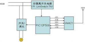
The hardware composition block diagram of the lighting control part is shown in Figure 1, and the interface circuits of each part are as follows:

Figure 1 Wireless lighting control circuit

Figure 2 Non-isolated power supply circuit diagram
① The non-isolated power supply circuit provides working voltage for MCU and wireless modules. As shown in Figure 2, PI’s LinkSwitch-TN is adopted. Since the power MOSFET and the controller are integrated in one IC, the design process can be greatly simplified. The number of components used in the circuit is very small, and no transformer is required. That is, the quick design part can be used to complete the design of common output voltage and current using standard components.
②The connection circuit of the wireless module is shown in Figure 3. The PHY only needs to use 5 I/O ports to work. At the same time, the SPI-compatible control interface is used as the data communication interface. Our test board also uses this method to interact with the PHY module. Connected. The functions of each interface are as follows: SCK: SPI serial port clock input; SDI: SPI serial port data input; NSEL: SPI chip select input (active low); SDO: SPI serial data output; NIRQ: interrupt request output (active low) ; PHY module is used as data. This module has the advantages of small size and low power consumption, and is very suitable for use in wireless devices.

Figure 3 Wireless module connection circuit
③The dimming module circuit is shown in Figure 4, including an EMI filter, a passive power factor correction, ballast control and lamp resonance output stage. The output stage adopts PWM output driving signal and drives the half-bridge MOS tube through the driving transformer. , Realize the control of the light.

Figure 4 Dimming control circuit
2.2 The hardware composition framework of the handheld RF remote control part
The hardware composition framework of the handheld RF remote control is shown in Figure 5. The specific circuit interfaces are as follows

Figure 6 Button circuit
①The button circuit is shown in Figure 6,
The 4*4 touch button is used as the user’s input, and the input judgment of the user’s button is to use the ordinary I/O method. The specific definition of each button can be determined according to the design needs of the development.
②The connection circuit of the wireless module is basically the same as that of the handheld RF wireless module and the light control part. The circuit is shown in Figure 3, and both use SPI to communicate with the wireless module.
③The power supply circuit is shown in Figure 7. The handheld remote control uses 5V-9V dry batteries to supply power to the system.

Figure 7 Power supply circuit
2.3 Light control software composition frame
The software flow is shown in Figure 8, which is divided into system initialization, main loop flow and interrupt service routine. Each function description is as follows:
①MCU initialization function: Including MCU timer setting, PWM setting, interrupt setting and input and output setting of each I/O port, etc.
②IA4421 initialization: set each register of IA4421, including setting of frequency, transmission rate, transmission power, frequency offset, etc.
③The main loop program: It mainly includes the detection of wireless signals and the detection of working current and voltage.
The main loop program is the basic control part of the software. It is an infinite loop program. Through this series of management functions, it continuously detects the occurrence of events and performs corresponding functional operations. Contains many subroutines, such as: Check if it’s time to execute events (timer time event processing), communication handshake recognition, address recognition, PWM output processing, current and voltage sampling processing, power management, etc.

Figure 8 Software flow chart
2.3 Framework of handheld RF remote control software
The software flow chart is shown in Figure 9. The software system includes: MCU initialization, variable initialization, IA4421 initialization, and loop detection of the main program.
The main loop program includes user key input detection, wireless data transmission, wireless signal reception and feedback data processing, correct transmission of user input information and timely feedback of light control status back to the handheld device, allowing users to see at a glance.

Figure 9 RF remote control software flow chart
3. Summary
The intelligent lighting control scheme introduced in this article can be universally applied to any smart home design scheme and can be conveniently applied to various smart home systems.
[ad_2]


