[ad_1]
With the development of my country’s automobile industry and the improvement of people’s living standards, more and more automobiles are entering ordinary households. Due to the frequent occurrence of various sudden road traffic accidents and car thefts, people are paying more and more attention to car safety and anti-theft. The development and research of automobile safety and anti-theft systems is an effective technical measure to ensure driving safety and prevent theft. Compared with the traditional single independent automobile tire pressure monitoring system and the automobile remote keyless entry system, the feature of this system is that the tire pressure monitoring system is integrated with the remote keyless entry system, which effectively realizes the recovery of the radio frequency (RF) module. It not only saves hardware overhead, but also improves the integration of the system.
1 Car security anti-theft system based on RFID technology
Radio Frequency Identification (RFID) is a non-contact automatic identification technology. The car security anti-theft system uses radio frequency identification technology to automatically identify target objects and obtain relevant data through radio frequency signals. RFID technology uses radio frequency transmission, which can read chip data through external materials to achieve non-contact operation. The communication data uses encryption algorithms to encrypt the data to achieve safe data storage, management and communication. With the rapid development of electronic technology and the improvement of the integration of electronic chips, the cost of RFID systems is also continuously reduced, which has accelerated the promotion and application of intelligence in the automotive electronics industry.
The smart car security anti-theft system consists of a tire transmitter module, a remote key module and a base station module. For RFID systems, the size of the transceiver frequency determines the recognition distance of the RFID system, the difficulty of circuit implementation, and the cost of hardware design. In the design of automobile security and anti-theft, low frequency (LF) frequency bands such as 125 kHz are used for short-distance, low-speed, and less data requirements for the identification of automobile engine anti-theft systems; ultra-high frequency (UHF) frequency bands such as 434 MHz are used for long-distance detection. Recognition of distance radio frequency communication system (automobile tire pressure monitoring system and remote keyless entry system).
2 System composition
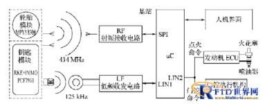
The overall structure of the system is shown in Figure 1. The system consists of a tire module, a key module and a base station module.

Figure 1 Overall block diagram of the system
Take a car with 4 tires as an example. The system consists of 4 tire modules, 1 key module and 1 base station module. The base station module includes RF receiver, LF transceiver, central control part, man-machine interface, and transmission Car area interconnection network (LIN) bus for ignition and gate control commands. The 4 tire modules are respectively installed in the 4 tires of the car to measure the pressure, temperature and battery voltage parameters of each tire in real time, and send the measured data to the base station module through RF communication for processing. The base station module, on the one hand, receives the RF data from the tire module, and further determines whether the tire parameters are normal, and gives a real-time alarm if abnormalities are found; on the other hand, it receives the RF control data from the key module and verifies whether the key ID is legal. If an abnormality is found, an alarm will be issued in time. If it is normal, the base station will send a confirmation message to the door control actuator to realize the opening/closing action; at the same time, the base station module communicates with the key module through LF communication, using the password of the transponder in the key module Match with the password in the base station module to control the start of the engine to achieve the purpose of anti-theft. The base station can be connected to other electronic systems inside the car through the car bus to share data and control information in real time.
3 System hardware design and implementation
3.1 Tire module circuit
The tire module is composed of tire state data acquisition and transmission circuits, as shown in Figure 2.

Figure 2 Tire module circuit
The tire module circuit uses Freescale’s intelligent embedded sensor MPXY8300. This series of sensors integrates the company’s low-power S08 core, containing 512 bytes of RAM and 16 KB Flash, and also integrates low-power capacitive pressure and temperature Sensor and single-channel low-frequency input interface. Its RF transmission supports two carrier frequencies of 315 MHz and 434 MHz, and can be programmed to configure the register as amplitude shift keying (ASK) or frequency shift keying (FSK) modulation mode. It also integrates a charge pump function. When the battery voltage is low, the power supply voltage of the RF transmitting part can be increased, so that it can still reach a certain R F emission intensity.
MPXY8300 is a system-on-chip (SOC) that integrates pressure and temperature sensors, 8-bit microcontrollers (MCU), RF transmitters and dual-axis (XY) accelerators on one chip. MPXY8300 pressure measurement range: car 100~800 kPa, truck 100~1 400 kPa, temperature measurement range: -40~125 ℃.
3.2 Key module circuit
The key module chip adopts PCF7961 produced by NXP Company.
PCF7961 is a reduced instruction set (RISC) processor based on the low-power 8-bit MRKII architecture, which integrates a UHF transmitter and LF frequency transceiver chip. This chip can complete radio frequency transmission and low-frequency communication authentication of the transponder, and is suitable for remote control anti-theft devices for motor vehicles. It uses a fast mutual authentication algorithm, uses random numbers, keys and passwords, and has the characteristics of high sensitivity (long distance) and short authentication time (39 ms).
PCF7961 also provides a 32-bit identification code (ID) that has been cured before leaving the factory. Figure 3 is the circuit schematic diagram of the key module.

Figure 3 Key module circuit
3.3 Base station module circuit
The base station module is mainly composed of radio frequency receiving circuit, low frequency transceiver circuit, main control chip MCU, LIN interface and man-machine interface. The radio frequency receiving circuit adopts the UHF radio frequency receiving chip MC33596 of FREESCALE Company, after completing signal demodulation and data Manchester decoding, the data is transmitted to the base station main control chip MC9S08DZ60 for data processing (RKE data decryption) and command execution.
The low-frequency transceiver adopts the PJF7992 produced by NXP. The PJF7992 integrates all the necessary functions to facilitate the reading and writing of the transponder. The base station microprocessor controls the communication between the PJF7992 and the transponder through the LIN serial interface of the PJF7992.
The main control chip of the base station adopts MC9S08DZ60 produced by F RE E SC AL E, which can configure and communicate the parameters of the radio frequency receiving chip MC33596 through the SPI serial bus. MC9S08DZ60 integrates 2 SCI (LIN) modules, which can control the low-frequency transceiver chip PJF7992 through a LIN bus, and the other LIN bus can transmit commands to the engine electronic control unit (ECU) and gate control related actuators. The LIN bus interface is added to the automobile security anti-theft system, which enables the system to share data and control information with other electronic control systems in the automobile, which greatly improves the security and flexibility of the system.
4 System software design
4.1 Wireless communication protocol
The wireless transmission adopts FSK modulation mode, and its Manchester encoding and decoding are automatically completed by the on-chip hardware. The door control commands in the tire module and the key module send data in the form of data packets (frames), and the data frame formats are shown in Table 1, respectively.
Table 1 RF data frame format of tire module

Table 2 Key module RF data frame format

4.2 Tire module software process
When the car is at a standstill or at a low speed, even if the tire pressure changes, it will not pose a threat to safe driving. At this time, signals such as pressure and temperature may not be collected or the number of collections may be reduced. The process is shown in Figure 4.
After the system is powered on and reset, the initial configuration starts to measure acceleration and judge the state of the car. If the vehicle speed is below 25 km/h, it will enter the dormant state and judge the state of the vehicle again after a delay; if the vehicle travels at a speed greater than 25 km/h, it will enter the normal working mode for signal acquisition, processing and transmission . Then it returns to the acceleration measurement state after a period of sleep delay.

Figure 5 Key module software flow
4.3 Key module process
The user can open and close the door by sending radio frequency data through the button switch on the key module. For the security of the system, rolling code encryption is performed on the sent data, and it enters the stop mode after sending. The software flow of the remote control door lock is shown in Figure 5.
4.4 Base station module process
When the car is not started, the base station module performs the remote control door lock function and needs to monitor the RF door control signal from the key module (the user presses the button on the key). When the remote control key is inserted into the ignition lock and rotated to the starting position, the transponder in the key and the PJF7992 of the base station module perform ignition verification, and then transmit the command to allow starting through the LIN bus. After the car is started, the base station module enters the tire parameter monitoring mode. By setting a reasonable polling interval, the number of RF responses of the tire module can be reduced, and the system power consumption can be reduced. The software flow is shown in Figure 6.

Figure 6 Base station module software flow
5 Conclusion
This article proposes a vehicle security anti-theft system based on RFID technology. The relevant function debugging has been completed on the test bench, and tire pressure monitoring, remote control door locks and engine anti-theft lock functions are realized. The LIN bus interface is added to the system. , Which enables the system to share data and control information with other electronic control systems in the car, which greatly improves the flexibility and safety of the system, saves system space, reduces production costs, and has a wide range of applications in the field of automotive electronics prospect.
[ad_2]


