[ad_1]
1 Introduction
Early car anti-theft systems were mainly composed of mechanical door locks and wheel locks. The function of the car lock has evolved from simply controlling the opening of the door to controlling the ignition and controlling the car’s circuit. With the development of modern electronic technology, the high-end anti-theft system that combines chip type and network type has been developed, which provides more effective anti-theft methods. This article uses RFUD chip technology and GSM module technology to design and make a car anti-theft system. Compared with other anti-theft systems, its main features are as follows:
(1) The new solution uses a chip with RFID (Radio Frequency Identification) technology. The chip has been set with a unique code when it leaves the factory and cannot be copied. The fourth-generation RFID chip used has a special diagnostic function, that is, the authorized person can obtain the historical information of the anti-theft system (such as the number of readings, time, etc.) when reading the secret information of the key. This type of RFID chip is now widely used Used in various advanced security systems.
(2) The use of network technology in the anti-theft system is currently one of the most advanced and effective anti-theft methods. It is the current widely used GPS (Global Positioning System) network alarm system.
The system installs a small wireless network terminal on the car, reports the vehicle’s operating position to the network center through the GPS module, and the monitoring center completes the scheduling and tracking. The disadvantage of this network system is that it needs to establish a wireless network monitoring center, signal relay base station, etc., generally requires manual services, end users have to pay a fixed fee on a regular basis, and its use area is also limited by the coverage of the wireless network.
This system adopts GSM module, utilizes mature GsM network to cover the whole country and even the whole world, is online 24 hours a day, and can lock stolen vehicles anywhere through program control. The system does not incur any costs when not in use, and is suitable for the general public. The RFID chip-type anti-theft device based on the GsM network can realize keyless entry, and can uniquely identify the vehicle controlled by the owner, and the probability of false alarm is smaller.
2 System structure and principle
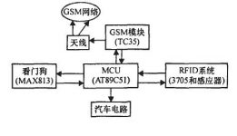
The system consists of three parts: radio frequency identification (RFID) chip, main control circuit (MCU), network interface module (TC35). The overall structure of the system is shown in Figure 1.

2.1 Radio frequency identification
A typical RFlD system includes a sensor, a reader, and a back-end computer that processes data. The sensor is also called a radio frequency card, which has the ability of intelligent reading and writing and encrypted communication. The reader sends a request signal to the sensor through the modulated RF channel, the sensor answers the identification information, and then the reader sends the received signal to the computer. The biggest feature of the system is non-contact identification, so it can identify multiple sensors and high-speed moving electronic tags at the same time. In this system, because the sensing distance is not required to be very far (0.1-5m), passive sensors are used, and the structure is simple, which is more suitable for carrying.
The reader selected for this system is TMS3705, which is a low-frequency base station integrated circuit produced by TI, which can be used as an RFID reader.
When the reader TMS3705 is connected to the power source, it will first transmit a certain frequency radio frequency pulse signal. If the sensor (the passive read-only sensor used in this system is m-TRP-RR2B) is within the effective sensing range, it will receive The signal is optimally coupled, and its capacitance is charged for the internal circuit of the inductor to work. When the sensor is working, it transmits data in FSK mode, and the radio frequency module receives and demodulates the signal, and then uploads it to McU for processing according to a certain communication protocol. If the sensor is a legal card, the MCU will send a command to the control unit to disarm and open the central door lock; if the sensor is an illegal card, it means that someone has entered forcibly with an illegal card, and the control unit will send a system alarm and pass the mobile phone module (TC35 ) Notify users by means of short messages.
2.2 Main control part
The main control single-chip microcomputer adopts the universal chip A duck 9C5l to reduce the cost. In the system, the main control MCU is responsible for user identification, signal detection, generation of various control signals and communication with the GSM module.
2.3 GSM network interface module
The communication network of this system uses GSM network. The TC35 module is used, which is a GsM wireless dual-frequency module with 4 transmission modes including voice, data, short message, and FAx. It belongs to the Gsbin GPRS module, supports all the functions of the GSM module, and also has permanent online functions, supports fast digital access and high-speed data transmission, and can realize uninterrupted tracking of the vehicle. Its functional structure is shown in Figure 2.

The 1℃35 module is mainly composed of 4 parts: GsM baseband processor, GSM radio frequency part, power ASIC, F1ash. The GSM baseband processor is the core of the entire module, which controls the transmission, conversion, and amplification of various signals in the module. . The GsM radio frequency part is a single-chip transceiver, which completes radio frequency reception and transmission. The GSM module current changes very large, which puts forward higher requirements on the power supply circuit.
The AsIc part of the power supply uses a linear voltage regulator to stabilize the externally input power supply voltage and rba + for the GSM baseband processor and the GSM radio frequency part. In addition, it also outputs a 2.9 μm 0rnA voltage for other circuits outside the module. use. The power amplifier of the GSM radio frequency part does not require high power supply voltage, so the external input voltage is directly used to store some user configuration information, phone book, etc.
3 System hardware circuit design
The hardware circuit of the motherboard includes: RFID interface circuit, car control interface circuit, MCu control circuit, TC35 network interface circuit.
(1) RFID interface circuit The RFID interface circuit is composed of 4 wires, of which 2 wires are power and ground, and the other 2 wires are data and control wires. The radio frequency part uses a certain communication protocol for data transmission and exchange with the MCU, and the control wire is used. Control the flow of data.
(2) Car interface circuit The car circuit is connected to the MCu circuit by a 16-pin interface. Among them, the circuit output control description of each pin of the interface is shown in Table 1.

(3) MCu control circuit In the system, various control commands are completed by the control circuit, such as starting and cutting off the car circuit and oil circuit, as well as sound and light alarms. Among them, the circuit, the oil circuit and the control circuit of the turn signal are realized by the output interface of the MCU to control the corresponding relay. The alarm horn control circuit is realized by the MCU output interface control transistor.
The control circuit of the central door lock controller and the power window adopts photoelectric coupling device to realize isolation. The power supply is generated by the voltage of the 12V power supply of the car battery to 5V, and is equipped with 9V. When the power supply is cut off, the backup power supply supplies power to the motherboard, and at the same time generates an interrupt signal to notify MCu to send out an alarm signal.
(4) The network interface circuit GSM module TC35 and the main controller are connected by a serial port, and a certain baud rate is used for communication, which is simple and reliable.
[ad_2]