[ad_1]
Chapter 1 Overview
Due to the large number and wide distribution of power supply company substations, they have the characteristics of decentralization, varied geographical environment, wide coverage, and numerous users, and are easily affected by user capacity increase and urban construction. The monitoring of substations is of great significance to distribution automation management, line loss analysis, load forecasting, and power demand management.
The traditional solution is to install security systems, environmental monitoring systems, transformer monitoring systems, etc., but these systems have the following problems:
1. Each system operates independently, forming a monitoring “island” phenomenon, which cannot be effectively managed, nor can it achieve the effect of safety management.
2. The coexistence of multiple systems not only increases the investment cost, but also greatly increases the maintenance cost in the later period. In addition, the simultaneous operation of equipment from multiple manufacturers will also cause rags on the scene and waste the time and energy of the power supply company.
According to the actual situation of the power distribution room, combined with years of experience in the operation and management of substations and power distribution rooms, Dianke Hengtai adopts the Tip3000 core technology platform and the HT500 series of intelligent monitoring terminals to realize transformer operation monitoring, primary equipment monitoring, and power distribution monitoring , Environmental monitoring, security monitoring, heating and ventilation, lighting control and other functions, and can expand the functions of fire alarm, image monitoring and other functions by adding equipment.
The integrated environmental monitoring system of the opening and closing station takes wired or wireless communication as the core, completes the data collection and monitoring of station-side transformers, power distribution, primary equipment, environmental monitoring, access control, anti-theft alarm, heating and ventilation, lighting control, etc., and integrates the above The information is transmitted to the monitoring center.
The system adopts a hierarchical and partitioned distributed structure, and is divided into two parts: the station-side control host and the software system. The software system can be divided into three-level centers of province, city and centralized control station.
The system displays and controls all monitoring variables such as transformers, power distribution, environment, fire protection, anti-theft alarm, and access control on the main interface of the monitoring system. System monitoring provides two monitoring modes: electronic map monitoring and chart monitoring. The electronic map can realize hierarchical and hierarchical display in the area.
The terminal equipment can run offline, and the station-side equipment can still realize normal operation, swiping card to open the door, linkage alarm, equipment linkage control, and record storage in the case of network disconnection, server failure, etc.
The system can be set up for linkage between the various subsystems in the system; it can also be linked with the integrated automation system of the substation through hardware and software, and it should be able to realize user-defined equipment linkage, including on-site equipment operation linkage video, integrated automation system Alarm linkage access control video, etc. And can complete automatic closed-loop control and alarm according to the on-site requirements of the power distribution room.
All system operations and alarm confirmations retain detailed logs and generate corresponding reports.
Chapter 2 System Functional Requirements

Chapter III Design Principles and Specifications
3.1 Design principles
In the design, the following principles are mainly followed:
(1) The principle of reliability. This monitoring system adheres to the principle of system reliability from design concept to system architecture to product selection. After a system failure or an accident causes an interruption, it can ensure the accuracy, completeness and consistency of the data, and has the function of rapid recovery.
(2) The principle of safety. This monitoring comprehensively considers equipment security, network security and data security. Perfect security measures are adopted at the front-end to ensure the physical security and application security of the front-end equipment, and reliable methods are adopted to prevent illegal access, intrusion or attack behavior of the front-end equipment. The data adopts a combination of front-end distributed storage and centralized storage management in the monitoring center. Strict user authority control is adopted for data access, and abnormal fast emergency response and log records are well prepared.
(3) The principle of advanced nature. This monitoring system adopts today’s advanced technology and equipment, on the one hand, it can reflect the advanced level of the system, and on the other hand, the system has strong development potential.
(4) The principle of scalability. This monitoring system fully considers scalability, adopts standardized and modular design, so as to ensure the transparency and interconnection between the systems, and fully considers the connection with other systems, so that the system has the function of updating, expanding and upgrading.
(5) The principle of standardization. The design of this monitoring system strictly follows the international, national and industry standards of related technologies. The products used in the design are standardized, well-opened, and follow internationally accepted agreements to facilitate future use and maintenance.
(6) The principle of ease of maintenance. This monitoring system is easy to operate and maintain, and can easily perform various daily maintenance tasks and system configuration, upgrade, self-check, and recovery.
Chapter 4 System Overall Design
4.1 Overall system architecture
According to the spirit of documents such as “Substation Management System”, “Substation Operating Regulations” and “Electric Power Safety Production Regulations”, combined with our company’s actual application cases, using distributed and modular architecture, the system is divided into two parts: station equipment and software system.
The station-side equipment is based on the HT502 station-side monitoring host. This host has a 2U architecture (1U architecture can be satisfied if the amount of control is less), which can be connected to environmental sensors such as temperature and humidity, radio/infrared and other security equipment, one-way access control, 8-24 road lighting/air conditioning and fan control and other functions. And can realize image capture, SF6 leak alarm, fire alarm and other functions through extension.
HT502 uses TCP/IP wired or GPRS/CDMA and other wireless methods to network with the center.
4.2 Software Architecture Design
According to “Smart Substation Technical Guidelines” (Q/GDW_383-2009), “110kV~220kV Smart Substation Design Specification” (Q/GDW_393-2009), “330kV~750kV Smart Substation Design Specification” (Q/GDW_394-2009), etc. The spirit of the document, combined with the actual application cases of our company, adopts a distributed and modular architecture, and divides the substation intelligent auxiliary control system into a three-level center, six functional modules, and ten functional subsystems.
The three-level center is the three-level center of province, city, and centralized control station, or the three-level center of municipal dispatching, centralized control station and substation, which is configured and managed according to different actual conditions.
4.2.1 Tertiary Center
The comprehensive environmental monitoring system of the opening and closing station (hereinafter referred to as the “system”) is a hierarchical and partitioned distributed structure, constructed according to the three levels of the substation comprehensive monitoring regional master station system, regional master station, centralized control station, and end system, as follows As shown in the figure.
Note: At present, the actual use situation generally adopts the two-level monitoring mode of municipal center and centralized control station.
4.2.2 Six functional modules:
Management server
Authentication management server (cluster/distribution management)
Streaming media server (including gateway server)
Communication server (front-end equipment communication)
Recording server (recording, disk management)
Client (including decoding)
4.3 Networking description
At present, there are usually the following transmission methods for the monitoring system of the power distribution room:
1. Power distribution room with Ethernet: each power distribution room host needs an RJ45 network port and an IP address.
2. Only 2M optical fiber interface: Configure a 2M-Ethernet bridge to provide Ethernet interface through photoelectric conversion.
3. Power distribution room without Ethernet and optical fiber: You can choose the following two methods:
1) Leasing the nearest telecom operator’s Ethernet or optical fiber: suitable for places where the operator’s network connection in the community is more convenient.
2) Lease the wireless network of a telecom operator: using GPRS or CDMA, you can use the public network or form an APN private network. This plan requires payment of network usage fees to the operator.
3) Arrange a dedicated microwave communication network: In the power distribution room and the regional center such as the nearby substation, respectively configure and arrange microwave devices, and transmit through the converted Ethernet. This scheme has big problems in transmission distance and reliability in cities, and is mainly used in open areas without high buildings.
In short, through various technical means, equipped with Ethernet is the most optimized and lowest cost transmission method.
Chapter 5 Functional Subsystem
5.1 Transformer operation monitoring subsystem
(1) Collect the three-phase voltage, three-phase current, three-phase power (load), three-phase reactive power, three-phase unbalanced current, power factor, harmonics, and electric quantity of the transformer through the gateway meter to provide early warning and Analyze the fault information. The gateway meter refers to the total transformer meter, which is mainly the smart meter, which generally follows the technical specifications of the smart meter of the State Grid.
(2) Collect and monitor the temperature of the transformer core through the thermostat, and can link the fan. When the temperature is higher than the set value (this set value is related to the transformer, you need to refer to the temperature rise data of the transformer manual) automatically start the fan, and automatically stop the fan after the temperature drops, which can not only give an effective warning to the transformer temperature, but also increase it The life of the fan.
The temperature measurement of the transformer core is mainly measured by pre-embedded temperature measuring elements. If the transformer is not hermetically sealed, such as a dry-type transformer. The temperature probe can be placed on the surface of the iron core to measure the surface temperature of the iron core. For transformers that do not have embedded probes and are sealed (such as the commonly used S11 series oil-immersed transformers), there is no good way. Even using infrared instruments can only measure the temperature of the shell surface.
(3) Fan operating status monitoring function: Through the PT/CT sensor, the operating status of the fan can be monitored to prevent the fan from running for a long time, blocking and other abnormal conditions. Moreover, it can be judged whether the fan can work normally, for example, when the fan is started, but the fan is not running, it can be determined that the fan is damaged and need to be watched on site. The condition of the fan must be able to guarantee the life of the transformer.
(4) Analyze the collected parameters through mathematical modeling to monitor the health of the transformer. And upload it to the main power distribution station to provide a strong data basis for the establishment of transformer operating status monitoring, early diagnosis of transformer faults and transformer failure models for the master station.
(5) Fault and over-limit alarm information can be actively uploaded to the master station.
5.2 Primary equipment online monitoring subsystem
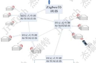
(1) Use temperature sensors to realize online real-time monitoring of the temperature of dangerous points such as cable heads and knife switches; (a wireless temperature sensor with zigbee communication can be used)
(2) The on-line monitoring of the cable head temperature adopts an indirect temperature measurement scheme. The approximate value of the heating temperature of the copper core conductor is obtained by measuring the temperature of the outer insulation layer of the cable head according to the environmental temperature correction value determined by the test in advance;
(3) Online monitoring of switch opening and closing times. By connecting the switch opening and closing auxiliary contacts, each time the switch opens and closes, the terminal device automatically counts the number of switching actions and uploads it to the power distribution master station;
(4) The primary equipment monitoring terminal should not have direct line contact with the primary equipment to avoid introducing new fault points and potential safety hazards.
5.3 Intelligent reactive power compensation monitoring subsystem
(1) Online monitoring of the data of the reactive power compensation system through the intelligent interface (if the monitoring of smart reactive power compensation needs to be realized, a reactive power compensation device must be configured);
(2) Using PT/CT monitoring module to collect the current and voltage of the low-voltage bus circuit;
(3) Real-time display of grid power factor, voltage, current, active/reactive power, voltage total harmonic distortion rate, capacitor switching status and fault warning;
(4) Monitor the action status of the switching device and record the number of actions of the switching switch;
(5) Overrun and fault warning function;
(6) When the power grid fails or a certain parameter exceeds the limit, the alarm indicator lights up and flashes, prompting the corresponding fault information.
5.4 Intelligent anti-condensation control subsystem of switchgear
Through the real-time precision monitoring of the temperature and humidity of the tested environment, and the intelligent control of heaters and fans, the environmental temperature and humidity indicators can meet the working requirements, and condensation can be effectively prevented. Mainly used in switch cabinets, outdoor terminal boxes, distribution boxes and other places. The main implementation schemes are as follows:
Real-time monitoring of changes in temperature and humidity of the measured environment. When the humidity reaches a certain level or the temperature changes sharply, and there is a possibility of condensation, the controller drives the heater and the fan to work, destroying the conditions for the condensation. When the conditions for the condensation disappear, the heater is automatically disconnected. The controller returns to the monitoring state.
There are two implementation schemes: the first is to use an independent anti-condensation controller, and the system is not networked for monitoring; the second is to use the intelligent interface of the auxiliary host to monitor temperature and humidity and control the heater and fan, which can be networked monitor.
5.5 Environmental Monitoring Subsystem
Through the application of acquisition and transmission technology, the environmental monitoring subsystem can monitor the working environment of some important places and equipment in real time (such as: temperature, humidity, water leakage, water level, smoke, open flames, etc.); when the working environment is abnormal, it can be Timely display, alarm, and data can be uploaded to the municipal and provincial dispatch centers through the network.
The main function:
1. Environmental data collection and processing functions: environmental temperature, environmental humidity, cable trench water ingress, water level depth, wind speed, smoke signal, open flame signal, etc.;
2. Automatic alarm and automatic troubleshooting of environmental parameters: when the monitoring center exceeds the preset value of environmental parameters, an audio-visual alarm is issued, flashing on the graphic display interface or electronic map interface of the platform, and automatic notification through voice and SMS On-duty maintenance personnel, and automatically print/archive troubleshooting data.
3. Alarm control function: When an alarm occurs, it can manually or automatically control the operation of the alarm speaker, sound and light integrated warning light, channel door, fan, and water pump according to the settings to protect and reduce the hazards;
4. Fault location and management function: According to the settings, the fault location can be located and managed on the electronic map.
5. Link detection function. Through the heartbeat monitoring settings, the system can monitor the lower computer equipment and communication lines in real time, automatically diagnose the equipment and link failures, and display them on the interface in real time.
6. Historical information query of environmental monitoring data, condition monitoring data and remote control data.
7. Query of employee operation log;
5.6 Equipment control subsystem
The system provides control functions for equipment such as air conditioners, fans, lights, and water pumps.
1. Air-conditioning energy-saving control function
Manual control function: You can remotely control the startup, shutdown, heating, and cooling of the air conditioner in the monitoring center through a computer, and the temperature value of the air conditioner can be directly adjusted. Intelligent air-conditioning controllers can automatically adapt to more than 600 air-conditioning models, avoiding the trouble of learning and debugging codes one by one for learning air-conditioning controllers on the market (for example, if the temperature control range is 18-28 degrees, then at least learn[28-18]* 2=20 times, and if a learning fails, you will have to restart it. And after learning, you need to re-debug at least 20 times, which is very troublesome and easy to make mistakes).
Directly remotely control the opening and closing of the fan, and you can also set the timed opening and closing of the fan. Each fan can be set up to five automatic time periods per day.
Automatic control function: By setting the upper and lower limits of temperature and humidity and the difference between indoor and outdoor temperatures, the air conditioner can be automatically controlled to close and open, and to close and open the fan.
2. Lighting control system
1. Manual control: The computer in the monitoring center can remotely control the light to turn off and on.
2. Alarm automatic control: According to the set conditions, the light will be automatically turned on for the alarm signals generated by the infrared detector, the perimeter alarm and the electronic fence.
3. Flexible control of the arming and disarming time group of the light signal (for the uniformly mapped perimeter, electronic fence and other alarm linkage lights, the linkage time section can be set to control the non-linkage of the alarm during the day, reducing resource consumption and saving energy. ).
3. Drainage control: Automatic or remote control of the drainage system is realized by monitoring the water level and sensor control of key locations.
Four, other control functions
1. Heater control
2. Sound and light alarm control: remote control start and close to avoid disturbing people.
3. Other equipment control
5.7 Access Control Subsystem
1. System overview
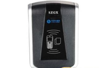
The access control system refers to an intelligent management system that is based on modern electronics and information technology, installs an automatic identification system at the entrance and exit of the power distribution station, and implements the release, rejection, and recording operations of people (or objects) in and out. It uses non-contact smart cards or fingerprints to replace the traditional manual verification of documents to release and use keys to open the door. The system automatically recognizes the identity information and access control authority information on the smart card. After the access control point swipes the card, the access control point can automatically open the door and allow entry and exit, otherwise it will refuse to open the door and output an alarm signal for illegal intrusion.
Since the access control authority can be changed at any time, no matter how the personnel change and flow, the access control authority can be updated in time, and there is no risk of embezzlement when the key is opened. At the same time, access control records are kept in a timely manner, which can provide a direct basis for investigating security incidents.
The HT502 station-side monitoring host includes one access control, which can be directly connected to the card reader, electric lock, and button to achieve the access control function.
2. Detailed functions of the system
1) Support three modes of multi-person authorization, multi-door authorization and compound authorization
2) Support 26 programmable dates, each time group includes 5 time periods, and the starting value of each time period is arbitrarily defined.
3) The system supports dual-mode operation of real-time monitoring and offline operation.
4) System support personnel enter and exit time personnel records.
5) The system provides equipment or network failure alarms, illegal intrusion alarms, door open overtime alarms, illegal card swiping alarms, and duress alarms. All alarms will display red flashing records in real time on the main control computer, drive the computer speakers to remind the administrator to pay attention, and link with the monitoring system.
6) The system supports multiple door opening methods such as card, password, card + password.
7) The system provides functions of forced door closing and emergency door opening through the central software.
8) The system supports setting the door normally open time for all doors or a single door, etc.
9) The system supports multi-card authentication to open the door.
10) The system supports lock and open timeout alarm function
11) The system supports real-time monitoring of electronic maps
12) The system has multiple records such as attendance, password opening, IC card opening, exit button opening, lock timeout alarm, door opening timeout alarm, disconnection alarm, illegal door opening alarm, and duress alarm.
5.8 Anti-theft alarm subsystem
The anti-theft alarm system reflects the deployment, fortification, alarm and various states of the detector in real time through flexible configuration, and prompts the alarm information in time. Perform intrusion monitoring within the set defense time. And the alarm system can be linked to the area’s lighting system, closed-circuit television monitoring and access control systems at the same time.
Manual arming and disarming and automatic arming and disarming (each zone can be set for 5 time periods)
Combining hardware can control the arming and disarming of each subsystem (user) of the alarm host.
The system can be connected to various alarm detectors such as vibration, infrared detection, equipment displacement (for transformers, external air conditioners and other equipment), and send them to the management center/maintenance personnel on duty in time when an alarm occurs, so as to grasp the status of the substation in real time.
The lighting system can be linked, and the image can be captured. If there is an intrusion, the alarm will be driven and the searchlight will be turned on in time to deter. If you install a video system, you can start image capture.
Intuitive electronic map display after alarm
The zone map, defense zone map, and sub-defense zone map can be set according to requirements
Relevant maps can be popped up after setting the alarm as needed
Linked cameras, access control, etc. can also be set on the map, and can be controlled directly on the map
Customizable voice prompt after alarm
Complete event record for subsequent inquiry
5.9 Video surveillance subsystem
The video surveillance subsystem is divided into two schemes. The first is that in the power distribution room without Ethernet, a serial camera can be used, and it is usually not recorded. When an alarm occurs, it can be linked to capture, and the captured image can be transmitted to the central platform. . The second solution is a power distribution network with Ethernet, which can completely adopt a digital monitoring system to achieve professional monitoring functions.
1. Alarm snapshot monitoring:
(1) Install a security camera to monitor the real-time situation of the switching station/distribution room;
(2) Support frame rate, code stream, resolution can be parameterized through the software operation interface, or can be automatically adjusted according to the preset scheme;
(3) Alarm linkage camera function: Supports the linkage of multiple alarm categories such as accident alarm, fire alarm, anti-theft alarm, fire alarm, power equipment flooding alarm, access control alarm, illegal intrusion and screen abnormality alarm, etc. Photo upload function; when an alarm occurs, it can link related equipment, such as starting a siren, etc., after the related equipment is started, it will automatically shut down within a set time; after an alarm occurs, the security camera of the switching station/distribution room will report to the client and The monitoring center sends alarm information and starts the camera function at the same time;
(4) Illegal break-in application can be set: set the monitoring range, when a suspicious person breaks in, link the alarm, take pictures, etc. and alert the main station;
2. Professional level monitoring:
The professional video surveillance system is based on digital hard disk video recorder hardware equipment, and takes network video centralized surveillance system management software as the core to perform powerful system functions.
(1) Video surveillance
1) Real-time monitoring, distributed monitoring, the name of the person swiping the card, and the superposition of environmental data characters when alarming.
2) Select the video to be monitored in a tree-like manner based on the region -> regional monitoring center -> monitoring area -> camera (multiple cameras can be divided into one main and multiple auxiliary according to the monitoring target), and the area can be monitored in real time All video information can be monitored in real-time on multiple channels (1, 4, 9, 16) in the same area and real-time monitoring of the same screen on the same machine; multi-angle video of a device can be monitored at the same time;
3) Different regional inspection centers can only monitor the videos under their jurisdiction;
4) Multi-angle real-time video (referred to as multi-angle video) of multiple cameras of one device can be monitored at the same time by clicking on the floor plan carried by the electronic map or the schematic diagram of the connection of a device;
5) You can directly view related videos according to the arming, disarming, and alarm status on the floor plan;
6) Multiple monitoring workstations and Web users can monitor any video at the same time;
7) With the video automatic reset function, you can set the default surveillance position of the camera. Under normal conditions, the camera maintains the default position; the default surveillance position will be restored within the set time period after the control is completed;
8) With video automatic patrol function, video patrol inspection of the monitoring points of the system, the objects participating in the patrol can be set arbitrarily, including different videos, the same different camera, different preset positions of the same camera, etc. The patrol interval can be Set, the camera that completes the patrol task can be automatically reset;
9) Manually record any video, and capture and store any frame of real-time video as JPEG, JPG or BMP pictures.
(2) Video management
1) Remotely set the recording rules of the front-end system to realize manual recording, timing recording, alarm-triggered recording, and screen abnormality detection recording of the front-end system;
2) It has a centralized storage function to realize the centralized storage of video and accident video in the event of a serious alarm in the IP SAN of the regional master station, using a video streaming storage strategy in seconds;
3) Simultaneous display, storage and retrieval of multiple videos of each selected camera;
4) Unified management of local and historical videos and pictures in a human-machine interface mode, which can be retrieved according to combined conditions such as alarm events, time periods, cameras, storage locations, etc.; any historical video can be uploaded from the station-side system, and local and historical videos can be deleted ;
5) Remote playback of historical video (time optional), alarm recording and local recording of any camera; playback methods include frame-by-frame, slow playback, constant speed, fast, and progress bar drag and drop;
6) It has the ability to replay video single frame capture and continuous capture, and can mark pictures for easy searching.
(3) Data forwarding
1) It has the ability to forward data such as video stream, station-side video, control information, alarm information, and voice intercom stream;
2) Support multiple communication methods such as IP unicast and forwarding multicast.
(4) Voice intercom function
1) Front-end scene recording, playback, save, and playback voice;
2) Realize real-time two-way voice intercom and voice broadcast between the center and the front end;
3) Realize the alarm broadcast function;
(5) Remote control
1) Remotely control the video monitoring equipment of the front-end system;
2) Adjust and control the camera’s angle of view, orientation, focal length, aperture, and depth of field;
3) For cameras with preset positions, they can be directly preset and operated;
4) After the control operation of the camera is completed, immediately release the control authority;
5) Set and query the camera’s preset position;
6) It has control functions such as opening, closing and disarming any door at the front end.
7) The front-end arming/disarming control can be carried out. The arming/disarming can be carried out automatically by the system according to the strategy that can be formulated in advance, or the arming or disarming control can be carried out through the floor plan;
8) Control is divided according to user priority, users with high priority can unconditionally obtain control of users with low priority, and users of the same level obtain control according to the principle of time priority;
(6) Alarm management
1) Video occlusion: When someone or an object moves near the camera and causes occlusion, the system will automatically deal with it. According to the set sensitivity, arming and disarming response time, occluding the alarm area and other rules, it will trigger the linkage alarm output, sound Alarm, alarm upload center..
2) Video masking: In order to protect the privacy and legal rights of others during the monitoring process, the areas that are not required or forbidden to be viewed within the video monitoring range can be set as private areas to be masked with masking blocks.
3) Video loss or abnormality: It is inevitable that there will be video loss or abnormality during the monitoring process. When the above situation occurs, the alarm output, sound alarm, and alarm upload center will be triggered according to the set alarm processing method.
4) Front-end equipment abnormal warning: When the front-end equipment has hard disk full, hard disk error, network cable disconnection, IP address conflict, illegal access, video input and output video format mismatch, the system will automatically deal with it, according to the already set Quotation processing method, linkage sound alarm, alarm upload center, linkage alarm output.
5) All alarm information is displayed in the alarm window in real time. The display content includes date and time, area and plant name, associated primary equipment or monitoring equipment, alarm content and other information; different levels of alarm information are displayed in separate colors, and the colors can be displayed. Settings; can be displayed according to the hierarchical partition classification, and the prompts and selections can be classified in card mode;
6) Realize alarm linkage, switch the specified camera video according to the alarm signal position, operate the specified equipment (lighting, etc.), and automatically record (recording time can be set);
7) Realize the automatic mobile phone SMS alarm function for serious alarms;
8) Flexible alarm information filtering and classification methods should be provided, and corresponding filtering conditions and classification methods should be set for different areas, users and workstations;
9) Administrators and monitors with alarm information confirmation function; confirmation should be based on authority and area, and the confirmation and processing of events and alarms in different areas are relatively independent;
10) All alarm information and confirmation information (including confirmation time, confirmation node, confirmation user, etc.) should be automatically saved and can be printed out;
11) It should have the alarm function of alarm bell and siren linkage;
12) Comprehensively query historical alarm information according to the combination of time, location, and alarm type.
(7) Video recognition and motion detection
Realize functions such as video recognition, border warning (including video loss, cordon, warning zone, intrusion detection, etc.), and realize corresponding alarm linkage.
(8) Video analysis and interactive functions
1) Intelligent video analysis: crossing the warning surface, entering the area, leaving the area, regional intrusion, picking and placing of items, wandering, gathering of people, illegal parking, fast movement. (Need to configure a dedicated DVR for video analysis);
2) Modify linkage rules online;
3) According to the linkage information, start recording, and have the pre-recording function, the pre-recording time can be set;
Note: This subsystem supports mainstream hard disk video recorders such as Haikang, Dahua, and digital camera series products. Therefore, the product will not be introduced separately.
5.10 Linkage configuration subsystem
1. Fire-fighting linkage: the fire-fighting linkage system of the central station and sub-stations, the controller is connected to the fire-fighting system signal. Once an alarm occurs, the system can link to the image monitoring system and send an alarm signal to the central management system. At the same time, it can be as needed The corresponding door lock is automatically opened.
2. Alarm SMS voice linkage configuration: support the configuration of SMS prompts, voice broadcasts, sound and light warnings, and on-site broadcast deterrence for various types of alarm points.
3. Linkage capture and video recording and query function: you can query the capture video according to various conditions such as capture type, record type, linkage type, alarm condition, capture area, and time. The captured video is stored on the central server in real time, which can avoid video loss caused by damage to the front end.
5.11 Inspection Management Subsystem
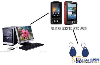
All access card readers can be used as patrol card readers. The access controller can record card swiping information and download the data to the computer for storage after connecting to the PC. The patrol software on the computer can make statistics of various patrol reports by department, individual and date based on these card reading data, which is convenient and quick. Any card reader access control point can be set as a patrol point, which is convenient and practical, and economical and cost-effective. On the basis of the already used access control system, without increasing the hardware cost, it only needs to add a set of inspection software to realize the inspection computer management function, avoiding a large amount of manual processing caused by inspection facilities such as clocks. It saves labor resources and improves the efficiency of power station management.
Use the existing equipment and network of the access control system to patrol, manage and supervise the unmanned substation by the staff of the power station.
Combined with the work ticket management system of the construction unit, it realizes timing, location, positioning, appointment and remote authorization operation management, which can effectively prevent unauthorized personnel from entering non-workstations and unauthorized operation areas, and avoid copying the door key and the person who receives the key from entering at will Potential safety hazards in substations.
[ad_2]