Prison RFID tool management system solution
[ad_1]
1 Overview
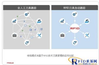
Since prison labor tools are at risk of being used by prisoners for illegal purposes, it is necessary to manage the tools. Traditional prison tool management uses manual methods, which are not efficient. RFID technology is used to achieve effective management of tools and reduce the risk of illegal use of tools.
2 Classification of prison tool management needs
The management of prison labor tools can be roughly divided into 3 categories according to different scenarios:
Tool management solidified on the work surface. Such tools need to be monitored in real time whether they are on the work surface.
Management of tools borrowed and returned every day. Such tools are usually placed in the workshop toolbox, distributed at work every day, and recycled after get off work.
Sporadic tool management. Such tools are usually placed in a tool warehouse, loaned out when used, and returned when used up.
3 RFID electronic label technology selection analysis
RFID electronic tags are divided into passive UHF tags, 2.45G active electronic tags, and 125K+2.45G multi-frequency active tags. The analysis of its performance and user experience is as follows:


4 RFID tool management application scenarios and processes
According to the aforementioned tool management requirements and the performance characteristics of RFID electronic tags, different scenarios adopt different RFID technologies for tool management.
4.1 RFID management of tools solidified on the work surface
1) RFID electronic tag selection
Tools solidified on the work surface need real-time on-site monitoring, using multi-frequency (125K+2.45G+13.56M) active RFID tags, with RFID reading equipment, to achieve on-site monitoring, leaving the signal coverage area, that is, an alarm.
2) Equipment deployment
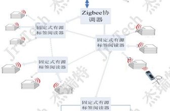
By deploying a low-frequency calibrator and a fixed reader in the work surface area, the coverage is shown in the figure below. The coverage area of the low-frequency scaler is a circular area with a radius of 1-4m, and the reader is a fan-shaped area with a radius of 80m.

3) Application process
Multi-frequency active RFID electronic tags are installed on the tools, and they are installed by sticking or lanyards. If the tags are illegally removed, the system will alarm.
The low-frequency calibrator interacts with active RFID electronic tags in real time to monitor whether the RFID electronic tags are in the coverage area, and if they leave the signal coverage area of the calibrator, an alarm is issued.
The background can display the status of the tool.
4.2 RFID management of workshop toolbox tools
1) RFID electronic tag selection
According to the management requirements of toolbox tools in the workshop and the characteristics of RFID technology, the RFID electronic tags of toolbox tools in the workshop adopt 900M UHF passive RFID electronic tags, which are bundled or pasted on the tools.
2) Equipment deployment
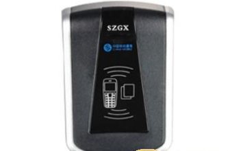
Built-in RFID reader and IC card reader on the tool distribution table in the workshop. The RFID reader realizes the reading of the tool RFID electronic tag, and the IC card reader realizes the identification of the tool adopter, and realizes the binding of the tool borrowing and returning and the identity of the person.
The tool issuance countertop display displays tool borrowing and returning information.
3) Application process
Fix the label with heat shrink tube, screws, etc. for tools with high frequency of use. For tools that are small in size and cannot be labeled (such as needles) are regarded as mini-tools, they should be labeled in units such as boxes or packages.
When applying for the tool, the prisoner swipes the identification IC card, the manager issues the tool, and places it on the RFID reader to read the tool’s RFID electronic tag data, and the system automatically binds the tool and personnel through the software;
When returning the tools, the prisoner swipes the identification IC card, and the manager collects the tools, places them on the RFID reader to read the tool RFID electronic tag data, and the system automatically releases the binding between the personnel and the tools through the software.
The computer monitor on the tool distribution counter automatically displays the information of the tools that have not been returned.
5 System Architecture

6 System software logical structure diagram and platform functions
The logical structure diagram of the system software is shown in the figure below:

The system software adopts a hierarchical and sub-module framework design. The presentation layer is exchanged with users for interface display, data entry, display, etc., the business logic layer is responsible for business process processing, and the data access layer provides a unified interface for data access. B/S three-tier structure, a multi-tier business software system based on WEB applications. The use of middleware technology to separate the central database and applications provides an easy-to-expandable business architecture, which can better and more rationally plan business and data flows, improve the security and reliability of the system, and have superior real-time data performance. Strong maintainability.
The platform functions are as follows:
System management: realize system configuration management, including authority management, role management, user management, etc.
Equipment management: realize configuration management and real-time status monitoring of all equipment
Regional management: Realize regional data and regional authority management, and realize hierarchical and sub-authority management.
Personnel management: realize personnel information synchronization and personnel information management
Label management: realize label warehousing management, label and personnel binding, label loss report, card replacement and cancellation management, etc.
Tool management: Tool basic information management and binding with RFID electronic tags.
Tool borrowing/returning management: tool borrowing/returning, tool borrowing/returning status, alarm management.
Tool-in-place monitoring and management: Realize the display of the status of the in-place monitoring tools and alarm management.

Multi-frequency active RFID electronic tags
Operating frequency 125KHz / 2.45GHz ~ 2.5GHz / 13.56MHz
Card number ID / IC mode
Working mode 125K low frequency trigger / 2.45G signal transmission
Trigger distance 0 ~ 3.5m adjustable
Lithium manganese soft pack battery, capacity 500mA, battery life> 5 years
Working current 4uA
Protection grade IP65
Size 23x40x9mm
Anti-dismantling alarm lanyard
Working temperature -40℃ ~ +60℃

Scaler
Working frequency 2.45GHz~2.5GHz/125KHz
Low frequency trigger radius 0~3.5m
Power supply DC12V/1A
Protection grade IP65
Working temperature -30℃~+60℃
Storage temperature -40℃~+80℃
7 Equipment specifications
900M UHF passive electronic label
Protocol: ISO18000-6C
Chip: Impinj Monza4QT
Storage space: EPC 96bit, User memory 512bit
Frequency: 902-928MHZ
Substrate material: use engineering plastics as tag carrier
Reading distance: about 4-7 meters (fixed machine 1W, 6DB) about 3 meters (handheld machine)
Weight: 6 grams
Applicable temperature: -40-80 degrees

Desktop RFID reader
Working frequency band: 840-960MHz
Labeling protocol: EPC C1G2/ISO18000-6C
Frequency hopping speed: <2s
Rated power: 30dBm
Output power: 5-30 dBm adjustable
Channel: 4 channels
Working temperature: -35℃~+65℃
Storage temperature: -45℃~+85℃
Data interface: RS232/RS485/interface
Ethernet (100M) interface
External I/O: 2 relay outputs, 2 I/O outputs (can be configured as Wiegand 26), 2 I/O inputs, 1 12v power output
Working voltage: 12v

The antenna specifications are as follows:
Frequency range 902-928MHz
Circular polarization
Gain 5dBi
Wave resolution 60°/18°
Characteristic impedance 50Ω
Standing wave ratio≤1.3
Front-to-back ratio ≥20dB
[ad_2]


