[ad_1]
1. RFID technical description
1. Documentation
The purpose of this program is to let integrators, engineers and users understand the design concepts, principles, overall planning and how to play a huge role in personnel positioning of the Internet of Things RFID positioning technology, and elaborate on the working principles and installation locations of related Internet of Things equipment. Information, so that integrators, engineering companies, and users can correctly understand the revolutionary changes brought about by the Internet of Things in the field of personnel positioning and the current deficiencies of the technology, and establish a correct understanding of the Internet of Things in the field of personnel positioning. If you encounter any confusion or confusion during the reading process, please contact Beijing Boyan Xintong Intelligent Technology Co., Ltd. Beijing Boyan Xintong Intelligent Technology Co., Ltd. has the final right to interpret this document.
2. Introduction to semi-active technology
Semi-active RFID products, combined with the advantages of active RFID products and passive RFID products, under the trigger of the low frequency 125KHZ frequency, let the microwave 2.45G play its advantage. Semi-active RFID technology, which can also be called low-frequency activation trigger technology, uses low-frequency short-distance precise positioning, microwave long-distance identification and upload data to solve the functions that pure active RFID and passive RFID cannot achieve. Simply put, it is to activate positioning at a short distance, identify and upload data at a long distance. Truly achieve the demeanor of a general of “strategic strategy, decisive victory thousands of miles away”.
3. Term abbreviations and explanations
RFID/Radio Frequency Identification: A communication technology that can identify specific targets and read and write related data through radio signals without requiring mechanical or optical contact between the identification system and specific targets
Semi-active electronic tag: frequency band 2.45G composite 125K technology, the tag has been in a dormant state before it enters the working state, which is convenient for the extension of the battery life of the tag; when the tag enters the reading area of the reader, it will receive the radio frequency from the activator at the same time The signal encourages and enters the working state.
Low-frequency activator: in real-time addressing state, real-time “active” detection of the surrounding active electronic tags, and send its own ID code and antenna ID number to the active electronic tag receiving module.
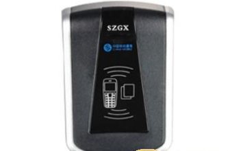
RFID reader: Receive and demodulate the radio frequency signal sent by the electronic tag (including the ID information of the tag, the ID code of the activator and the ID number of the antenna, etc.)
Electronic anti-detachment wristband: The semi-active electronic tag is made into a wristband type. When the electronic wristband is removed, the wristband that can send out an alarm message is called an anti-detachment electronic wristband
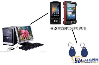
Handheld reader: Also called handheld terminal, it can receive the wireless signal sent by the positioning tag, and display simple information of the person wearing the tag on its own screen.
4. Comparison of semi-active RFID personnel positioning compared with other personnel positioning technologies
Compared with active RFID products:
Semi-active RFID products do personnel positioning management, the positioning accuracy is more accurate, and can be located in each room; to achieve the same positioning accuracy, semi-active RFID products, the cost is much less, to achieve the same effect, the cost is basically active RFID Half of the product;
Semi-active RFID products have a smaller recognition distance error, about 10cm, while active RFID can only be a rough fuzzy distance, the signal is erratic, and there is no way to be accurate;
Semi-active RFID tags are usually dormant, do not consume electricity, and are very power-saving. The battery can be used for 5 years, while active RFID tags usually continuously send signals and consume a lot of electricity.
Relative to GPS satellite positioning:
Semi-active RFID product positioning can accurately locate each room in each building, while GPS positioning can only reach a certain building in a certain street, a certain district in a certain area of the city.
Relative to mobile phone area positioning:
Semi-active RFID product positioning can accurately locate each room in each building, while mobile phone positioning can only go to a certain building in a certain street, a certain district in a certain area of the city.
To sum up, in comparison, the semi-active RFID technology products have their unique advantages in terms of economic cost, positioning accuracy and effect. It is also the first choice of Beijing Ph.D. for semi-active RFID technology. As the reason for the company’s core technology.
2. Analysis of personnel positioning requirements
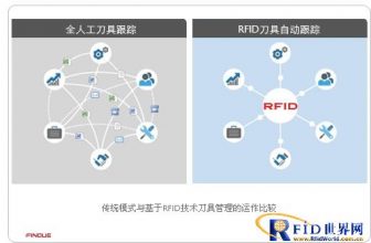
1. Demand analysis
The current traditional personnel management mode has the following problems: the area is relatively scattered, and multiple people are required for on-site management; the distribution of personnel cannot be known in real time, and the location of personnel cannot be determined (whether they leave without authorization, etc.); they cannot be managed to everyone; When it comes to a dangerous situation, the location of the personnel cannot be determined in time; the trajectory information of the personnel cannot be viewed. The traditional personnel management model is not only low in management efficiency, but also cannot fundamentally solve the problem of supervision to everyone. Although the application of semi-active RFID technology personnel positioning system can fundamentally solve the problems of personnel management. Semi-active RFID technology not only solves the problem of on-site management by multiple people, but also greatly improves work efficiency. This mode can greatly improve the management mode and reduce the cost of personnel management.
2. Personnel positioning functionality
real time monitoring
Real-time monitoring of the map, which can display the distribution of personnel and equipment
Personnel query positioning
The personnel information can be queried and located, and the positioning error is within 5 meters
Personnel history replay
It can replay the historical trajectory of the personnel, perform animation display, and replay the trajectory route of the personnel from one area to another area
Call the police
When people in the area gather illegally, leave the designated area or enter the illegal area without authorization, the system will alarm
Video linkage
The linkage between RFID technology and existing video can view the scene of the accident in real time, providing a basis for the deployment of relevant personnel to solve emergencies
3. System introduction:
1. System principle
The semi-active RFID technician positioning system uses RFID electronic tags as the most advanced identification code at present. It has the characteristics of not easy to break, reliable data, long service life, and long effective communication distance. It is a substitute for barcodes and infrared rays. The best choice for logos. Install it on the controlled target to be the unique identification of the target for tracking and positioning.
At work, managers use networked wireless identification base stations to track and locate targets.
a. Semi-active RFID electronic tags
The semi-active RFID electronic tag integrates the advantages of the active RFID electronic tag and the passive RFID electronic tag as a special marker. In normal conditions, it is in a dormant state and does not work, and does not send RFID signals to the outside world. Only when it enters the activation signal range of the low-frequency activator, the tag starts to work.
b. Working principle of semi-active RFID automatic identification
Combined with a low-frequency activator, a semi-active RFID tag works normally after being activated. The activation distance of the low-frequency activator is limited. It can only be accurately activated at a small distance and a small range. In this way, the low-frequency activator is used as the base point for positioning, and different base points are installed in different positions, and then used for a long distance in a large area. The reader recognizes and reads the signal, and then uploads the signal to the management center using different upload methods. In this way, the entire process of signal collection, transmission, processing, and application is completed.
c. Personnel positioning principle
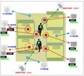
Schematic diagram:

As shown in the figure above, we use RFID semi-active technology for personnel location management. In each monitored area, such as each room, install RFID readers. Each reader has its own device number. When in the room, the electronic tag worn by the person is read by the reader in the room, so that it is judged that the person is in the room; at the same time, install a low-frequency activator in every four rooms in the corridor, extending out 4 channels Antenna, a low-frequency activation antenna is installed at the door of each room, so that when people move in the corridor, they will be activated by different low-frequency activator antennas, so as to realize the judgment of people’s corridor movement.
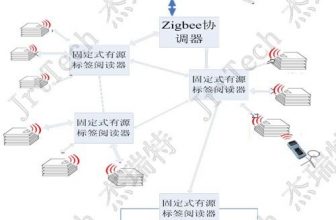
2. The overall structure of the system
a. System composition and architecture
The personnel area location management system based on semi-active RFID technology is composed of semi-active RFID electronic tags, semi-active low-frequency activators, readers (receivers, electronic monitoring base stations), network equipment, computers, servers and system software. The following figure shows the system architecture of a simple personnel area positioning management system:

System network structure
b. Schematic diagram of system area positioning

As shown in the above figure: through the address codes of the activators uploaded by different activated tags, the situation of the people near the different activators can be judged, including the number of people, names, positions and other information. In this way, no matter where people go, there will be a local activator lock them to determine their specific location, and timely upload the information to the management center, the management center through a series of transformation processing, and get relevant results. At the same time, we also easily accomplished our established goal, which is to manage the regional positioning of personnel.

Schematic diagram of equipment installation located in the room
c. Schematic diagram of system floor positioning

As shown in the figure, install an all-in-one machine at each corridor entrance, and then extend two low-frequency activation antennas (the antennas have different IDs), and place them all the way on the upper corridor and the other on the lower corridor. When it is activated by different activation antennas, the reader receives the tag information with the activator ID to determine which floor the person is on.

Schematic diagram of equipment installation located on the floor
d. Boundary positioning design
Some special personnel are located in the fence area where people are not allowed to approach. It is necessary to install two activation borders along the fence and locate the base station. The distance between the two activation borders is preferably not less than 4 meters. The first activation border can be used. Installed inside the wall, outside the wall, and inside the wall, but keep away from high-voltage wires, and the distance to the crimping line should not be less than 3 meters, and do not touch other metals, such as iron fences, lamp posts, etc., which should be 10 The distance above cm, as shown below:

Boundary antenna 2 is arranged outside the wall, and boundary antenna 1 is installed inside the wall

Schematic diagram of the signal area formed by the boundary antenna
e. Access control management system

Schematic diagram
As shown in the figure above, we install a low-frequency activator for each access control that needs to be managed. Each activator leads to 2 low-frequency activation antennas, namely No. 1 antenna and No. 2 antenna, which are arranged on the outside and inside of the door. A 2.45G long-distance reader/writer independently developed and produced by our company is installed next to the access control as a signal receiver. When a person wearing a semi-active RFID low-frequency activation tag enters the door, they are activated by the activation antenna No. 1 and the activation antenna No. 2, so that the system judges that the person has entered the door. On the contrary, the system recognizes that it is going out. This completes the management of the entire access control system personnel entry and exit judgment.

Installation diagram of access control equipment
f. Concealed installation of equipment
When installing the equipment, we can make full use of the basic conditions of the installation site and flexibly grasp the installation method. Generally, our active antenna is installed on the ceiling and installed secretly to form a beautiful and concise style.

4. Semi-active RFID system software introduction
1. Front desk login interface
Through a dedicated user name and password, you can enter the foreground management interface for system operation;
2. Software interface navigation diagram

3. The overall process of tracking and positioning monitoring

4. Backstage management login interface
Back-end management login interface, to control the system database, personnel information, equipment information, area management, etc.
5. Personnel File Module
Establish a digital file of each person, record various information of each person in detail, and establish a multi-dimensional query system, which can query various information simply and quickly. The original personnel information system can be integrated to realize information sharing. Recording the daily behavior of the managed personnel can comprehensively analyze their behavior patterns.
Administrator information: including tag ID, personnel number, name, gender, certificate name, certificate number, certificate address, postal code, contact phone number, personnel level, personnel category, status, remarks, photos, resumes, characteristics;
Add, modify, delete, and query personnel data.
Personnel information includes: personnel unique system ID, electronic tag ID number, personnel number, name, gender, certificate name, certificate number, certificate address, certificate address postal code, contact address, contact address postal code, contact phone number, identity level, Authorization group ID, actual authorization string, and controlled object status.
For example, the personnel ID or name can be entered in the management terminal to quickly locate the personnel.
It includes five parts: personnel information management, administrator information management, monitoring equipment management, electronic map management, and monitoring area management.
6. Real-time location monitoring of personnel
7. Real-time people counting, electronic roll call
8. Illegal entry into important areas
9. View the location of designated personnel
10. Track playback
11. Equipment Management
Equipment information: including equipment ID, equipment number, equipment name, equipment IP, category, location, status, remarks;
12. Label data management
Maintain and manage wristband tags, add, delete and modify. The activation and termination of the wristband tag can be set.
13. Electronic chart management
Maintain and manage the electronic map, add, delete and modify, and refine it to specific floor rooms.
Note: The electronic map part needs to be discussed separately.
14. Area Management
Management strategies can be set to maintain, manage, add, delete and modify specific areas. An area has independent locator ID, receiver ID and repeater ID, and has a maximum capacity.
[ad_2]