[ad_1]
introduction
At present, domestic traffic signal lights generally adopt fixed-cycle program control technology, which mainly depends on experience and past statistical data to determine when the traffic lights turn on and off. To realize the intelligentization of road traffic, it is necessary to introduce variable-cycle traffic signal light control technology to detect traffic flow and congestion at intersections in real time, and dynamically adjust the signal lights according to the rules to obtain a more satisfactory traffic rate.
This paper proposes a design scheme for a traffic signal light control system with distributed characteristics. It uses RFID technology to improve the accuracy of road condition information collection, uses current loop long-distance transmission, and applies artificial intelligence theory to make the system more adaptive And scalability.
1 System function and overall structure design
From the perspective of functional characteristics, the intelligent traffic signal system should have signal control modes such as time fixed mode, time setting mode, time sensing mode, on-site remote control mode, remote control mode, etc.; it can be used for date, time setting, and time setting. , Induction parameter setting, cycle time, phase difference and green signal ratio and other parameter settings; can perform system self-check, green conflict detection, lamp failure detection, line failure detection; powerful input/output function, can realize intersection Different phases of light control output and detection function. In addition, the system provides a friendly man-machine interface, users can set and control the signal machine through manual switch, keyboard or remote control.
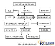
The semaphore is the core of the entire system. It is composed of 5 kinds of functional module plug-in boards, including LCD screen, control board, lamp driver board, switching power supply, and button board, as well as power distribution board and terminal block. This system selects the ARM core-based 32-bit embedded RISC processor AT91RM9200 as the signal machine control board processor, which can meet the requirements of signal machine intelligence, so that the signal machine can be used in the system to collect and process traffic flow data, communication networking and area Coordinated control platform.
The structure diagram of the intelligent traffic light system is shown in Figure 1.

The signal light uses light-emitting diodes, that is, LED technology, which has high luminous power, strong shock resistance, and power saving and stability. All components in the system, including signal lights, are powered by external power and equipped with UPS. The signal light controller does not provide working voltage for various signal lights, only transmits signals, and fully realizes weak current control. The brightness control of the signal lamp adopts the principle of pulse width modulation. The voltage is full-wave rectified, divided by resistors, and converted into a square wave with a certain duty cycle by an optocoupler. When the power supply voltage increases, the duty cycle will decrease. Small, inhibit the increase of LED brightness, when the power supply voltage is reduced, the duty cycle will increase, limiting the decrease of LED brightness, thus realizing the automatic control of LED brightness.
The long-distance communication control of the signal lamp can be realized by the current loop signal transmission method. This kind of long-distance communication control circuit is simple, low cost, and strong anti-interference ability. It is the three kinds of signals that are transmitted serially shifted by the current loop-data D, clock CLK, and latched STR. The traffic light converts the serial information sent by the controller into parallel output, and accurately realizes bit control. Signal lights can be connected in parallel, so that the load capacity of one line output is enough to control more than a dozen signal lights, which can meet the needs of various traffic intersections.
The intelligent traffic light system is not only an independent system, but also a part of the intelligent signal light system of the entire region. Through information sharing, linkage control of traffic signals can be realized, and effective traffic prediction and guidance can be carried out. When the traffic flow at the intersection is relatively uniform and stable, the coordinated operation of the signal lights in the area can achieve “green wave band” control.
{$page$}
The structure diagram of the regional traffic signal light linkage system is given below, as shown in Figure 2.

2 System hardware design
2.1 The main control terminal module of the signal machine
The main control machine uses the processor AT91RM9200, which is an ARM-based ARM920T core and integrates a wealth of peripheral function modules, which is very suitable for real-time control, supports real-time operating systems, and has high computing speed.
The signal machine adopts 12/5V power supply, AT91RM9200 works at 3.3V and 2.5V, and other devices in the system choose working voltage as 3.3V and 5V.
The signal machine needs time synchronization in the system’s internal communication and regional coordinated control, so the RTC (Real Time Clock) is designed for time synchronization. AT91RM9200 integrates RTC unit inside, it only needs an external crystal oscillator to work, which is very convenient.
The main control terminal of the signal machine needs to store the boot program, the embedded operating system and its file system and application programs, as well as other data that needs to be saved during operation, so the storage space must be expanded through the external storage unit, including SDRAM, NorFlash and NandFlash. NorFlash is mainly used to store the bootloader Bootloader and the operating system linux kernel image. After the system is powered on or reset, the Bootloader runs from the FlashROM, and the Bootloader initializes the hardware and copies linux to SDRAM to run.
NandFlash is mainly used to store applications and data.
In order to facilitate the operation of the man-machine interface, AT91RM9200 has a built-in LCD (liquid crystal display) drive controller, which can automatically generate LCD drive control signals and can be directly connected to the LCD. The keyboard module expands a 4×4 keyboard matrix through ZLG7290B, and ZLG7290B connects with the processor through the IIC serial bus.
Taking into account the size of the signal machine, and in order to facilitate the upgrade and expansion of the equipment, the data bus, address bus and necessary control signals are derived from the signal machine control board, and a unified system bus is designed. The bus is used to dispatch and control various functional blocks, such as traffic flow. Information collection section, signal light controller section, infrared receiving section, fault detection section, etc. These boards correspond one-to-one with the corresponding functional modules, and are connected to the signal machine control board with a slot interface.
2.2 Vehicle flow information collection module
Radio Frequency IDentification, or RFID (Radio Frequency IDentification), commonly known as electronic tags, is a non-contact automatic identification technology that automatically recognizes the target object and obtains related data through radio frequency signals. The work process does not require human intervention and can be applied to various Harsh environment. A set of RFID equipment includes three parts: radio frequency tag, antenna and reader. The antenna and reader are placed on the side of the road. When a vehicle with a radio frequency tag passes through the road, the reader will receive and return the radio frequency modulated signal carrying RFID information through the antenna, and then send it to the main control terminal of the signal machine after processing. Complete information collection of road condition data. The relevant data is also sent via the local signal machine to the host computer-the control end of the regional signal light system. The traffic flow information is modeled and calculated in the main control terminal of the signal machine, and the cycle time required by the current signal light can be obtained.
2.3 Emergency intervention module
Load remote control circuit in the system to support emergency intervention with infrared remote control. Using 8-channel infrared transmitting/receiving special integrated circuit BA5104/BA5204, it can transmit 6 continuous signals and 2 single signals. The serial port is convenient to access, and the price is low, and the stability is strong. The infrared receiving terminal is connected to the signal machine control board bus, which can transmit the remote control key signal to the signal machine main control terminal for interrupt processing, and has the highest priority.
{$page$}
2.4 Fault detection module
The working environment of traffic signal lights is more complicated, and there may be various unpredictable power supply, electromagnetic interference and random obstacles of the signal machine itself. In order to ensure the reliable operation of the system, in addition to software countermeasures, a hardware watchdog reset circuit MAX708CPA is specially introduced. This device has functions such as μP reset, power-down monitoring, manual reset, etc., which can play a better protective role. In addition, using the fault detection circuit with voltage detection and current detection, real-time detection of the signal light controller and the signal light, and the returned TTL level signal is transmitted to the signal main control board, and the signal system can choose to continue to execute according to different results , Or alarm up, or even shut down by itself.
2.5 Signal light controller module
The signal light controller is the necessary hardware connection between the signal machine and the signal light. The various light color states of the intersection signal lights are transformed by the signal light controller processing the signal data.
2.6 Regional linkage module
The local signal light system and the management end of the regional signal light system adopt a local area network (LAN) for two-way communication. The local signal machine control terminal encapsulates the data information to be processed through the Web Service application program interface and sends it to the regional signal lamp system control terminal. The processing work is completed by the latter, and then the final result is returned to the local signal machine. Web Service technology makes full use of the computing power of the local signal light system control unit, reduces the processor overhead of the local signal machine, and makes the signal light system more stable and easier to maintain.
3 software implementation
The main program flow chart is shown as in Fig. 3.

Figure 3 The main programflow chart
The traffic signal system program can be divided into the following modules:
The semaphore main program module is the main module of the entire system. It uses the execution results of other modules according to priority to generate the current semaphore cycle.
{$page$}
The timing control program module supports the input of a fixed time value through the keyboard, changes the current signal lamp cycle, and combines manual experience with the system to reflect the human-computer interaction capability.
The traffic flow adjustment program module uses RFID technology to identify the traffic flow near the traffic intersection, through GA (genetic algorithm) and introduces fuzzy logic theory[6], Carry out real-time analysis and calculation of the traffic situation at the intersection, and adjust the signal lamp cycle according to the result. In this system, this module is also the most intelligent part. In addition, through the expansion of RFID technology, namely the Automatic Vehicle Identification Management (AVIM) system, the vehicle flow information is connected with the vehicle information monitoring and management center to form a vehicle information management platform.
The timing adjustment program module is set for the road sections that have formed a certain road condition rule. It is possible to preset different signal light cycles for different times of the day at one time. For example, if the traffic volume is low at night, you can adjust the timing to change the traffic lights to flashing yellow lights. When the designated time comes the next day, the traffic lights will be automatically restored.
The yellow flashing warning program module can immediately interrupt all the traffic lights and change them to flashing yellow lights. It is mainly used during periods when the traffic volume is small, which can improve the traffic efficiency.
The remote control forced program module is designed for the traffic police to direct traffic on the spot. You only need to use the remote control to press a specific button on the infrared receiving end to force reset the signal light phases on the spot. It is especially suitable for one-way traffic jams. Adjust and quickly pass through intersections with vehicles that require barrier-free traffic such as ambulances and firetruck.
The linkage processing program module is used to process the instructions sent by the upper computer (the control unit of the traffic police linkage center). After the signal lights are connected to the network, the traffic intersections in the entire area can be coordinated and linked. If a congestion occurs at an intersection, the linkage center can issue instructions to appropriately extend the traffic time of the traffic lights in the direction of the adjacent intersections to effectively clear the traffic.
The “watchdog” program module can generate an overflow signal when the main program is running abnormally, and send a reset signal to the processor through the pin to restart the main program.
The system detection and alarm program module is set in response to the signal lamp failure. It makes a judgment based on the returned TTL level signal. Once a problem is found, the error information will be reflected upwards in real time to provide a basis for further system maintenance.
4 Conclusion
The development of an intelligent traffic signal light system can effectively improve the current traffic situation, increase the utilization rate of existing road resources, and save social costs. This system is based on the AT91RM9200 processor, is application-centric, and adopts an embedded operating system. The design has the characteristics of low cost, easy operation, convenient expansion, high information sharing, and strong flexibility. It has good reference value and high The practical value.
[ad_2]


